
Installation Guide
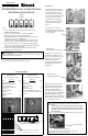
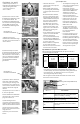

For Unit 1:
1) Remove the screw from the
sheet metal reinforcement plate
located at the bottom of the
water heater cabinet, and then
use it to secure the Control Board
to the water heater cabinet.
2) Connect the connector
from Communication Cable
to socket No. 1 on Control Board.
3) Connect the 4-pin connector
from Communication Cable to the
4-pin socket located at the top of
the water heater control board.
The Communication Cable ground
wire terminal should be grounded
with the PC board ground wire.
4) Remove the protective cap from
the 2-pin connector marked “MS”
(located in the middle of the water
heater wiring harness).
5) Connect the 2-pin connector
from Communication Cable into
the 2-pin connector marked “MS”.
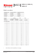
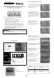
Kit Components
MSB-C3 (Pack D)
Parts List
Part Qty
Communication Cable
Instruction Sheet 1
1
Communication Cables (C3)
Water Heater
Control
Communication Cable (C3)
Control Board
MSB Communication cable (MSB-C2)
(9.8 ft, 3 m)
U306-1034(00)
MSB-C3
Note:
•
Up to 5 water heaters can be connected together using
the MSB-M and MSB-C3 kits.
United States & Canada: For use with Rinnai Tankless Water
Heaters (except for models V53e, V53i and R63LSe which must
use pressure activation valves, PVA).
•
Disconnect all water heaters from their power source before carrying out
the following installation procedures.
NOTE: The front cover panels of each water heater must be removed prior
to completing the following installation procedures.
WARNING
Please contact Rinnai if you have further questions on the
applicable water heater models.
•
•
When over 5 water heaters are connected together,
MSB-M units are connected using MSB-C2 kits.
•
If multiple MSB-M are used, then at least three water heaters
should be connected to each MSB-M.
Ex: With 7 water heaters, one MSB-M should control 4 water
heaters and the other MSB-M should control 3 water heaters.
070 00012 32077 9
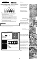
6) Repeat steps 2 to 5 for Units 2, 3,
4, and 5, as applicable.
Note: Communication Cable for
Unit 2 plugs into socket 2, Unit 3
plugs into socket 3, etc.
7) After making all of the
connections to the Control Board,
tighten all of the cable ties used to
secure the Communication Cables.
Ground all the Communication
Cables.
Master
2nd
3rd
4th
5th
Manifold Electronic Control System
Installation Instructions
Ground wire of
Communication Cable A
Ground wire of
Communication Cable A