Ubbink Ubbink bv P.O. Box 26 6980 AA Doesburg The Netherlands T +31 313 48 02 00 F +31 313 47 39 42 info@ubbink.nl www.ubbink.nl article code: 0072288 07/08 version 1.
Contents Introduction 3 Installation Requirements Approvals/codes 4 Do not use with other vent products 4 Inspection 4 Condensate 4 Recommended venting air intake terminal position 5 General Installation Instructions Joint connection 6 Coping with condensation 6 Appliance connection (male top) 6 Appliance connection (female top) 7 Condensate drain 7 Shortening of vent extensions 7 Parts & Dimensions 8 Installation Instructions Horizontal Discharge Vent System Identify the vent loca
Introduction The Ubbink Rolux® concentric vent system is considered part of the direct vent tankless water heater. The Ubbink Rolux® concentric vent system was tested and approved with the appliance by a third party testing agency. Check the manufacturer's installation instructions or certificate of compliance to confirm that the Ubbink Rolux® concentric vent system is approved for your direct vent tankless water heater. The tankless water heater installation instructions take precedence over this document.
Installation Requirements Installation and service of Ubbink Rolux® concentric vent systems must be performed by a qualified installer, service agency or the gas supplier. Approvals/codes The installation must conform with local codes or, in the absense of local codes, the National Fuel Gas Code, ANSI Z223.1/NFPA 54 and/or CSA B149.1, Natural Gas and Propane Installation Code. The maximum vent length, as stated in the water heater installation instructions and these instructions, should never be exceeded.
Recommended vent/air intake terminal position Terminals should be so positioned as to avoid products of combustion entering openings into buildings or other flues or vents H B ED FIX ED S O E L L C AB X ER OP B D E C V V B L V F ED FIX ED OS CL LE AB ER OP B V V B V I M X V K DETAIL INSIDE CORNER J G A V V A B CAUTION Maintain 12” of clearance above the highest anticipated snow level or grade or whichever is greater. Please refer to your local codes for the snow level in your area.
General Installation Instructions Joint connection Vent connections must be firmly pressed together so that the gaskets form an airtight seal. To complete the joint connection, secure with three #8x1/2" sheet metal screws. Secure the vent to the wall or ceiling with pipe clamps or perforated hanger iron. Coping with condensation Vent lengths greater than 5ft. should pitch a minimum 1/4"/ft. (1°) to the appliance. Note: see exception under Condensate on page 4.
B Condensate drain B D A D Condensate can damage the water heater, please read carefully page 4 in this installation manual. male appliance top C female appliance top C To prevent condensate from draining back to the appliance, a condensate collector (B) and trap (C) should be used. The trap must maintain 3" of fluid and the drain tube must pitch down from the appliance. Annually inspect the collector and trap for obstructions and fluid content in the trap.
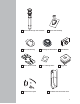
Parts & Dimensions for all Rolux® vent system components 4.
11 10 vertical discharge roof terminal 12 flat roof flashing 18 Flashing for Metal Roof 14 wall-thimble 15 Water Heater Guard 16 Pass Through Plate 17 bugguard 13 condensate trap kit 19 pitch roof flashing Outdoor Vent Extension Cover 9
1 Installation Instructions Rolux® Horizontal Discharge Vent System Identify the vent location CASE A: Installation with Male Appliance Top Case B: Installation With Female Appliance Top D = 5.5" (140 mm) D = 5.5" (140 mm) NOTE Cover the top of the heater to prevent debris from entering when cutting Steps: Case A: Place the horizontal Discharge Adapter on the appliance. Case B: Place the 90° Vent Pipe Elbow on the appliance.
3 Final installation of the vent system CASE A: Installation with Male Appliance Top Case B: Installation With Female Appliance Top NOTE First place innerwall plate to slide terminal through After cutting the appropriate length, slide the Horizontal Termination through the hole in the wall. Position the first rubber wall plate around the male end of the termination. Case A; Slide the male end of the termination in the Horizontal Discharge Adapter.
Horizontal Vent System Installation examples condensate direction 3 4 condensate direction 3 5 4 8 5 1 8 min. 1˚ (= 0.25 inch/ft) (= 19 mm/m) 7 Female appliance top 7 1 Male appliance top 13 13 condensate direction 3 4 condensate direction condensate direction 3 4 7 min. 1˚ (= 0.
1 Installation Instructions Rolux® Vertical Discharge Vent System Identify the vent location NOTE Cover the top of the heater to prevent debris from entering. Determine the location where the roof discharge terminal will be installed. Taking into account the angle of the roof, cut the hole with a dimension that allows the vertical discharge roof terminal to be installed (6"x6" hole for flat roof, 9"x6" hole for 12/12 pitch, or 12"x6" hole for 16/12 pitch).
3 Mounting the vent system Vent connections must be firmly pressed together so that the gaskets form an airtight seal. Secure the system with the supplied vent pipe clamp or perforated hanger iron.
Vertical Vent System Installation examples 10 10 12 11 10 5 11 Female appliance top 7 7 13 5 6 5 Female appliance top 6 13 5 8 2 13 Male appliance top 15