Hydronic Air Handler Installation and Operation Manual • • • • • • • • • • 1
Hydronic Air Handler Installation and Operation Manual
Thank you for purchasing Rinnai’s hydronic air handler. Before installing and operating the hydronic air handler, be sure to read these instructions completely and carefully to familiarize yourself with the features and functionality. This manual provides instructions for installing the hydronic air handler and is a supplement to the Rinnai Tankless Water Heater or Boiler Installation and Operations Manual supplied with the system.
This manual contains the following important safety symbols. Always read and obey all safety messages. Safety alert symbol. Alerts you to potential hazards that can kill or hurt you and others. DANGER Indicates an imminently hazardous situation which, if not avoided, will result in personal injury or death. WARNING Indicates a potentially hazardous situation which, if not avoided, could result in personal injury or death.
The hydronic air handler is designed to work with Rinnai tankless water heaters and boilers (models listed below) to deliver a wide variety of heating capacities for residential and light commercial applications. NOTE Refer to section “3.8 Specifications” for a complete list of product specifications. It is the responsibility of the installer to follow all national codes, standards and local ordinances, in addition to the instructions in this manual.
When transporting components of the hydronic air handler, follow the guidelines below: • Choose the correct hand truck to support the weight and size of the system components. Refer to section “3.8 Specifications” for specific weights and dimensions. Example: AH083CP AH 08 3 C P Blower Motor • Use safe lifting and material handling principles to prevent workplace accidents. P = 3-Speed PSC Motor • Use proper lifting techniques to load the equipment onto a hand truck.
Hydronic Coil Circulation Pump (for models with integrated pump). Circulates hot water between the air handler and tankless water heater/boiler.
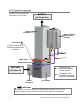
Example Vertical (Upflow with Side Return) Configuration SUPPLY (Air Flows Out) Supply Ductwork Rinnai Tankless Water Heater or Boiler Thermostat A call for heat from the thermostat activates the air handler Water Inlet Water Outlet RETURN Hot Water From Water Heater/Boiler into Air Handler Front Panel (Air Flows In) Cold Water From Air Handler Returning to Water Heater/Boiler Return Ductwork Air Handler IMPORTANT The ductwork in the above image is for representation purposes only; it is not a
The air handler is approved for the following configurations: • Vertical: Upflow with bottom or side (left or right side) return • Horizontal: Upflow with bottom return The air handler is not approved for the following configurations: • Do not position the air handler on its front panel.
AH083CP Installation Suitable for Potable Water Systems • • Circulation Pump Included Product Weight - lb. (kg) (approximate) Nominal CFM (Cubic Feet/Minute) Nominal Output Btu/hr at 140°F Rated Voltage Transformer Size and Type Blower Wheel (Diameter x Width) Blower Motor Type Blower Motor Hot Water Coil Rows Blower Motor Coil Material Blower Motor Horsepower (HP) Blower Full Load Amps (FLA) Water Connection Pump Voltage Pump Amps 9x6 in. 3 1/3 5.
AH083P AH084P AH125P AH206P Hydronic Air Handler (Internal Circulation Pump Not Included) Appliance Type Installation Indoor (approved for manufactured housing and mobile homes) Suitable for Potable Water Systems Yes • • Configurations Vertical: Upflow with bottom or side (left or right side) return Horizontal: Upflow with bottom return Circulation Pump Included No Product Weight - lb.
IMPORTANT This section is referring to domestic hot water recirculation in the plumbing system and not the circulation of hot water between the air handler and tankless water heater/boiler. Domestic hot water recirculation circulates hot water through the plumbing system so that instant hot water is available. Domestic hot water recirculation operates between calls for heat to ensure a balance of comfort for HVAC heating and domestic hot water.
Values shown in following tables may vary depending on the static pressure of the duct system.
• AH083P 120°F 140°F* 160°F Blower Speed (Btu/hr) Low Medium High 21,000 23,000 25,000 29,000 32,000* 35,000 38,000 42,000 45,000 AH084P 120°F 140°F* 160°F 23,000 32,000 41,000 25,000 35,000* 46,000 27,000 38,000 50,000 AH125P 120°F 140°F* 160°F 32,000 44,000 57,000 33,000 47,000* 60,000 35,000 49,000 63,000 AH166P 120°F 140°F* 160°F 41,000 58,000 75,000 42,000 60,000 78,000 44,000 62,000* 80,000 AH206P 120°F 140°F* 160°F 41,000 58,000 75,000 42,000 60,000 77,000 43,000 61,000* 78,000
Measurements: in. (mm) Hydronic Air Handler Models • AH083CP • AH084CP • AH125CP • AH166CP • AH206CP • AH083P • AH084P • AH125P • AH166P • AH206P A 17.5 (445) 21.0 (533) 24.5 (622) B 27.0 (686) 28.0 (711) 28.0 (711) C 20.5 (521) 20.5 (521) 20.5 (521) D 15.5 (394) 19.0 (483) 22.5 (572) E 16.0 (406) 16.0 (406) 16.0 (406) F 25.4 (645) 26.4 (671) 26.4 (671) G 21.5 (546) 22.5 (572) 22.5 (572) H 21.4 (544) 22.4 (569) 21.4 (543) I 16.5 (419) 17.5 (445) 17.5 (445) 2.
Universal Air Handler Rack Assembly Universal rack assembly that mounts to the Rinnai Tankless Water Heater or Boiler for simple installation with the hydronic air handler. Works with all Rinnai AH Series Hydronic Air Handler models. Includes hardware for mounting the tankless water heater or boiler to the air handler rack assembly, and hardware for assembling the rack.
⓫ ❶ ⓬ ❺ ❼ ❸ Models With Models Without Internal Internal Circulation Pump Circulation Pump 1 1 1 0 0 1 1 1 1 0 0 1 0 0 1 0 1 0 0 1 0 0 0 0 0 1 AH206P Hydronic Air Handler Installation and Operation Manual 1 1 1 0 1 0 1 1 1 0 1 0 0 0 1 0 1 0 1 0 0 0 0 0 0 1 AH166P 12 3/4" Sweat Flange Kit 1 1 1 1 0 0 1 1 1 1 0 0 0 1 0 0 1 0 1 0 0 0 0 0 0 1 AH125P Hot Water Replacement Coil With No Pump and Valve Assembly 1 1 1 1 0 0 1 1 1 1 0 0 0 1 0 0 1 1 0 0 0 0 0 0 0 1 AH084P 11 Rinnai Part # 607000033 60
Carefully unpack the air handler. If the unit is damaged, contact your local dealer/distributor. Do not attempt to use the air handler if it appears damaged. The blower section is factory assembled and all components are performance tested. The air handler consists of a blower assembly and controls in an insulated, galvanized steel factory finished enclosure. Knockouts are provided for electrical wiring entrance.
• • Unsuitable heating system water can cause the formation of scale or sludge, which affects system efficiency. It can also cause corrosion and reduce life of the heat exchanger. Clearances to combustible material is 0 in. to plenum and duct for first 36 in. (914 mm) and throughout the remaining ductwork system. Never use water that has been treated by a reverse osmosis, deionized, or distilled water to soften the water to fill the heating system.
• • This air handler is certified for installation in residential and light commercial applications and approved for the following configurations: − Vertical: Upflow with bottom or side (left or right side) return − Horizontal (upflow with bottom return) • All models are designed for indoor installation only. • These instructions are intended as a general guide only and do not supersede national or local codes.
• Install ductwork in accordance with NFPA 90B and any local codes. • Install the conditioned air plenum, ducts and air filters (not provided) in accordance with NFPA 90B Standard for the installation of Warm Air Heating and AirConditioning Systems (latest edition). • Isolation connectors (if utilized) must be nonflammable. • • Duct connections for the air handler with hot water heat must allow room for water piping connections to be made in the upflow configuration.
• Use copper conductors only. • All field wiring must be done in accordance with National Electrical Code, applicable requirements of UL and local codes, where applicable. • Electrical wiring, disconnect means and over-current protection are to be supplied by the installer. Refer to the air handler rating plate for maximum over-current protection, minimum circuit ampacity, as well as operating voltage.
Pipe Sizing Considerations WARNING Solder joints on domestic water lines must be made with NO-LEAD SOLDER. When selecting a pipe size for a given flow rate, the resulting average flow velocity should be between 2 ft. (0.61 m) and 4 ft. (1.22 m) per second. Thermal Expansion of Piping At water flow velocities of approximately 2 ft. (0.61 m) per second, flowing water will carry air bubbles along a vertical pipe. Average flow velocities of 2 ft. (0.
IMPORTANT Read section “4. Installation Preparation” before starting installation steps. Refer to section “4.5 Ductwork Requirements” for complete ductwork installation requirements. 1. Connect the supply air duct to the flange on top of the blower section of the air handler. Refer to the previous section (section “4. Installation Preparation”) for more information on location and configuration requirements. Example Vertical Installation 1. Place the air handler in the desired location and configuration.
Air Handler PCB W2 W1 W G G Refer to section “4.7 Electrical Requirements” for complete electrical requirements. Connect Spade Connector to “W” Terminal on Air Handler PCB Note: Electrical cables go through the knockout holes on the left or right side of the cabinet. See the images below for specific locations.
Cooling Application with Hot Water Heat Thermostat Refer to section “4.6 Thermostat Requirements” for complete thermostat installation requirements. 1. Mount the thermostat approximately 5 ft. (1.5 m) from the floor and close to, or in, a frequently used room, preferably on an inside partitioning wall or a section of wall without pipes or duct work. 2. Connect the thermostat to the air handler. Follow the wiring diagrams in the next section: “5.4.1 Thermostat Wiring Diagrams.
IMPORTANT Install the Rinnai Tankless Water Heater or Boiler by following the Installation and Operation Manual supplied with the unit. IMPORTANT If you are not installing the Domestic Priority Switch: • Skip this section and proceed to section “5.7 Connect Water Lines.” • Ensure not to short out the harness connectors that would normally be used with the Domestic Priority Switch.
4. Connect one end of the accessory cable to the accessory port on the PC Board. Connect the other end of the cable to the switch circuit board accessory port. Switch circuit board accessory port PC Board accessory port Accessory cable 5. For internal units, flip the switch circuit board to where the circuit board side will be facing the inside of the unit. External (Outdoor) Units Internal (Indoor) Units 6.
5.6.1.2 Wiring Instructions 1. Attach the harness plug from the Domestic Priority Switch (black, white, and red) as described in Table 1 (located on next page). 2. Install the hydronic air handler per the instructions in the “S-BMS/Air Handler Switch Installation Instructions.” Follow steps for a “Generic Air Handler.” 5.6.1.3 Set Parameter Instructions WARNING WARNING Ensure the power supply to the water heater and hydronic air handler is disconnected before starting installation.
5.6.2.2 Wiring Instructions Thermostat Wiring: Using the provided crimp connectors (B in image on previous page), connect the white and black leads of the switch circuit board to the “W” contact on the indoor thermostat and air handler (polarity is not important). See Table 1 below and the wiring diagrams in this section for additional details. The final crimp connector should be connected to the unused red wire lead on the switch circuit board. 5.6.2.
WARNING Ensure the power supply to the boiler and hydronic air handler is disconnected before starting installation. Removing the front cover will expose live mains voltage connections. IMPORTANT To prevent cold air from being produced, it is recommended to set Parameter 42 to “A - Continuous Run.” See the “Rinnai I-Series Boiler Installation and Operation Manual” for more information. 5.6.3.1 Install Switch Circuit Board 1.
5. Attach the air handler/OPU circuit board to the PC Board via double-sided tape. Ensure the circuit board does not make contact with the heat exchanger. 5.6.3.2 Wiring Instructions 1. Attach the harness plug from the Domestic Priority Switch (black, white, and red) as described in Table 2. 2. Check all wiring and reattach the front cover. Table 2: Domestic Priority Configuration Switch Configuration Generic Air Handler Required Leads/Wires Function White/Black Normally Closed 3. Reconnect power.
The domestic priority switch allows the tankless water heater or boiler to give priority to domestic hot water by shutting off the air handler when necessary. When used with a hydronic air handler, the switch gives priority to domestic hot water. When domestic hot water demand exceeds a certain point, the air handler will turn off to ensure the demand is met. To test this function: 1. Turn on the water heater/boiler and air handler. 2. Open the hot water taps until the air handler turns off. 3.
Domestic Priority Switch Domestic Priority Switch Y Y Single Stage Heat Pump with Auxiliary Backup Heat Single Stage A/C Cooling with Single Stage Heating Domestic Priority Switch Y Single Stage Heat Pump 34 Hydronic Air Handler Installation and Operation Manual
IMPORTANT • • • • Refer to section “4.8 Plumbing Requirements” for complete plumbing requirements. For standard installations, refer to the piping diagrams in sections 5.7.1 and 5.7.2. For more information on the tankless water heater or boiler plumbing connections, refer to the unit’s Installation and Operation Manual. Water connections to the air handler should follow all state and local plumbing codes. 1.
This is not an engineering drawing; it is intended only as a guide and not as a replacement for professional engineering project drawings. This drawing is not intended to describe a complete system. It is up to the contractor or engineer to determine the necessary components and configuration of the particular system to be installed. The drawing does not imply compliance with local building code requirements.
Recommended Rinnai Domestic Priority Switch Gas Supply Line Condensation Drain Line as Appropriate Aquastat Connection Cold Water Supply Line Thermostat Thermostatic Mixing Valve Rinnai Hydronic Air Handler with Integrated Pump and Check Valve Hot Water Outlets NOTE • Schematic does not apply to Rinnai Tankless Water Heaters equipped with recirculation capability: SE+ Series featuring ThermaCirc360™ models (Super High-Efficiency Plus RUR Models) • Wire solenoid to 24V valve connection on air handler.
Recommended Rinnai Domestic Priority Switch Condensation Drain Line as Appropriate Cold Water Supply Line Gas Supply Line Thermostat Thermostatic Mixing Valve On-Demand Recirculation Component (Push Button, Motion Sensor, etc.
Flushing the hot water coil prior to start up is required to remove any residual material from the installation or manufacturing processes as well as remove any air from the system. A bleed valve comes standard on all air handlers with factory installed circulating pumps. If using an external circulating pump, please use an external purge valve or other mechanism to flush hot water coil after installation.
Air Flow Inspection: • For proper cooling operation, the airflow through the indoor coil should be between 350 and 450 CFM per ton of cooling capacity (or 350 – 450 CFM per 12,000 BTU/HR) based on the rating of the outdoor unit. • The cooling blower speed is factory configured to provide correct airflow for an outdoor unit that matches the maximum cooling capacity rating of the air handler.
• When the thermostat calls for cooling, the thermostat circuit between R and G is completed. The normally open contacts close, causing the indoor blower motor to operate. The thermostat circuit between R and Y is also completed; this circuit closes the contactor in the outdoor fan motor. Thermostat circuits R and O, or R and B, energizes the reversing valve, switching it to the cooling position (depends on outdoor HVAC unit).
If the temperature of the water within the hot water coil were to drop below 40°F, the thermostat circuit between R and W is completed, activating the hot water circulating pump, external circulating pump or isolation valve. When the water temperature rises above 70°F, the thermostat circuit between R and W is opened and hot water will stop circulating within the hot water coil.
IMPORTANT Specific blower wire connections may vary by model.
The speed of the air handler is factory default set as per the table to the right. To adjust speed settings, follow the steps below: Default Setting Speeds Model Speed • • AH083CP AH083P Medium • • AH084CP AH084P Medium • • AH125CP AH125P Medium 3. Locate the PC Board. • • AH166CP AH166P High 4. On the PC Board, remove the wire lead from the “MTR” tap (this tap controls the fan motor speed). See ❶ in image below. • • AH206CP AH206P High 1. Disconnect power to the air handler.
Copper Diameter Fitting 3/4 in. 1 in. 90 Degree Elbow 2 0.75 45 Degree Elbow 0.75 0.3 Straight Through Tee 0.4 0.135 3 1.35 Reducer Coupling 0.5 0.18 Gate Valve 0.25 0.09 Ball Valve 2.2 1.29 Swing Check Valve 3 1.35 Multiplier Per Linear Foot of Pipe 1 0.3 Fitting 3/4 in. 1 in. 90 Degree Elbow 34.56 18.4 4.8 2.08 Side Port Tee 49.92 20.32 Reducer Coupling 8.32 4.32 Ball Valve 10.56 6.88 PEX x NPT 8.64 6.08 Multiplier Per Linear Foot of Pipe 3.2 1.6 3/4 in.
Models: • SENSEI™ SE+ Series (RU Condensing) • HE+ Series (RL Non-Condensing) • HE Series (V Non-Condensing) Entering Water Temperature Flow Rate 120°F 140°F 2 160°F 120°F 140°F 3 160°F 120°F 140°F 160°F 1 4 NOTE Tankless water heaters must have a minimum input rate of 160,000 Btu/hr. BTU Output Maximum Equivalent Blower (Air Handler Models) Pipe Length (ft.
Models: • i060C • i090C • i120C IMPORTANT If more than 40 equivalent feet of plumbing is needed with the I-Series Boiler, Rinnai recommends the use of hydraulic separation with an external circulation pump. Hydraulic separation uses primary/secondary piping to separate the boiler from the heating system. Hydraulic separator examples include a low loss header (field-supplied), closely spaced tee (field-supplied), or the Primary-Secondary Heating Kit offered by Rinnai (part # 807000212).