Installation & Servicing Instructions High efficiency condensing gas boiler CAUTION! Read this manual thoroughly before installing, servicing, putting into operation or using this boiler and vent system. WARNING! Improper installation, adjustment, alteration, service or maintenance can cause property damage, personal injury (exposure of hazardous materials)* or loss of life. Refer to the user's information manual provided with this boiler.
Contents of instructions These installation instructions contain important information for the safe installation, start-up and maintenance of boilers with capacities 50,000 BTU/hr. These installation instructions are intended for licensed professionals, who have the necessary knowledge and are approved for working on heating and gas systems.
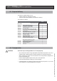
Content 2 3 4 5 6 Safety and general instructions ........................................................4 1.1 Designated use ...................................................................4 1.2 Hazard definitions ................................................................4 1.3 Symbol definitions ...............................................................4 1.4 The following instructions must be followed ........................5 1.5 Follow these instructions for the space heating water ....
1 Safety and general instructions Please observe these instructions in the interest of your own safety. 1.1 Designated use The boiler is designed for heating water for a central heating system and generating domestic hot water. The boiler is delivered with a burner controller (MCBA) preinstalled.The boiler can be fitted with a modulating outdoor reset sensor ARV12 (included with the boiler) or an On/Off thermostat or relay panel end switch (accessories). 1.
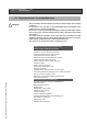
1.4 The following instructions must be followed - The boiler must only be used for its designated purpose, as described in the Installation Instructions. Each unit is fitted with a data plate. Consult the details on this plate to verify whether the boiler is compliant with its intended location, e.g.: gas type, power source and venting classification. Only use the boiler with the accessories and spare parts listed.
i NOTICE Chemicals that are corrosive in nature should not be stored or used near the boiler or vent termination. 1.5 Follow these instructions for the space heating water Unsuitable heating system water can cause the formation of scale or sludge, which affects system efficiency. It can also cause corrosion and reduce life of the heat exchanger. – You must follow Rinnai guidelines for boiler water quality. – Thoroughly flush the system prior to filling. – Follow the Rinnai cleaning instructions.
1.7 Relevant Installation, Service and User manuals – Approved vent system – User manual 1.8 Disposal – Dispose of the boiler packaging in an environmentally sound manner. – Dispose of components of the heating system (e.g. boiler or control device), that must be replaced in an environmentally responsible manner.
3 Description of the boiler Room sealed boiler The boiler retreives its combustion air from outside then discharges the flue gasses to the outside. Condensing Retrieves heat as much as possible from the flue gasses. Water condensates on the heat exchanger. Modulating Stepless higher or lower burning according to the heat demand. The Rinnai E50C boiler is a room sealed, condensing and modulating central heating boiler, with an integrated DHW fascility.
4 Packaging and transportation 4.1 Scope of delivery The boiler is supplied ready for use. • Please check if the packaging is intact. • Check if all the items listed are included in the delivery. The supply kit contents: Part No.
5 Installation 5.1 Requirements for the installation room ! DANGER - - Installation & Servicing Instructions Rinnai E-Series - 10 The room where the boiler will be placed must always be free from freezing conditions. Do not store or use gasoline or other flammable vapors and liquids in the vicinity of this or any other appliance. Never use or store any chlorinated detergents or halogenated hydrocarbons (e.g. in spraycans, solvents and detergents, paints, adhesives) in proximity of the boiler.
5.2 Fitting the boiler - Remove the packaging materials. Lay the boiler on its back during unpacking. Remove the casing from the boiler. This part can be left apart during installation. It must be placed on the boiler and fixed with the screw behind the door and in the 4 quick releases before the boiler is started up. i NOTICE - i NOTICE Turn the boiler to its side and remove the wall bracket from the back of the boiler by removing the 2 screws.
5.
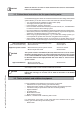
5.3.1 Clearances from boiler ceiling Min. 10" / 250mm 24" 600 2" 50 wall 15.
5.4 Technical specifications E-Series Combi E50C Boiler type Input Hs CH Qn Output non-condensing CH Qn Output EN677 efficiency CH Installation & Servicing Instructions Rinnai E-Series Qn Output AFUE CH 14 BTU/hr kW BTU/hr kW BTU/hr kW BTU/hr kW Efficiency at 98.6/86°F (36/30°C) part load, % Hs, EN677 CH AFUE according IBR % O2 (at full load) % Electr. power consumption max. W Electr. power consumption stand by W Current V/Hz Fuse rating A Degree of protection acc.
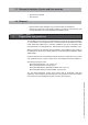
6 Connecting the boiler The boiler has the following connection pipes; - The central heating circuit pipes. These must connected to the system by means of 1" (22mm) adapter fittings. See further chapter 6.1; - The gas supply pipe. It is provided with a 3/4" male thread into which the tail piece of the gas valve can be screwed. See further chapter 6.4; - Cold and hot water pipes for domestic hot water (DHW).
6.1 Central heating system Connect the central heating system according to its instructions. The boiler pipes can be connected to the installation by means of compression fittings. Reducers should be used for connecting to thick-walled pipe (welded or threaded). i NOTICE When removing the plastic sealing caps from the pipes, dirty testing water may drain from the boiler.
- Boiler system flushing (Not Boiler heat exchanger) When replacing an existing boiler the heating system should be flushed with the old boiler in place before the new boiler is added to the system. If the old boiler has already been removed a bypass must be piped in when the new boiler is installed in order to facilitate the flushing of the system. The boiler must be valved off from the system, while the system is flushed.
11. If the installation is a zone system be sure to purge out each zone individually 12. Close the auto feed on the system (F1) 13. Close the return side purge station (BD2) and disconnect the hose (H3). 14. Open the main valve on the system return (V3) 15. Close the bypass valve below the boiler (V4). 16. Open shutoff valves on both the supply and return connections below the boiler (V1 and V2). 17. Clean out the dirt trap 18. Test the pH of the water that will be used for filling the system 19.
The boiler has a self-adjusting and self-protecting control system for the load and the pump capacity. By this means, the temperature difference between the supply and return water is checked and controlled. If the installation resistance is over the stated value; the load will be adjusted until an acceptable temperature difference between supply and return water has been obtained.
6.1.3 i NOTICE 6.1.4 i NOTICE Safety valve An ASME 30 psi pressure relief valve is included with the boiler and must be fitted before any shut off valve in the system. Low water cut off The Rinnai E50C boiler has a factory installed pressure switch type Low Water Cut Off (LWCO). Check your local codes to see if a Low Water Cut Off is required (LWCO) and if this device conforms to local code. The Low water cut off is not serviceable. 6.
6.4.1 i Gas connection with natural gas The gas supply connection must comply with local regulations or, if such regulations do not exist, with the National Fuel Gas Code, ANSI Z 223.1. For Canada, the gas connection must comply with local regulations or, if such regulations do not exist, with the CAN/CSA B149.1, Natural Gas and Propane Installation Code. NOTICE Pipe sizing for natural gas Contact gas supplier to size the gas supply line and meter.
6.5 Hot water supply Connection of the drinking water installation should be performed according to the national secondary drinking water regulations. ! DANGER Do NOT use toxic chemicals, such as those used for boiler treatment in potable water heating systems used for space heating. The sanitary water pipes can be connected to the installation by use of adapter fittings.
6.5.3 DHW Expansion Tank A domestic water expansion tank could be required by local code. Check local code to determine if it is required. If a combi boiler is installed in a closed water supply system, such as one having a backflow preventer in the cold water supply line, means shall be provided to control thermal expansion. Contact the water supplier or local plumbing inspector on how to control thermal expansion. 6.5.
6.5.5 Installing a valve kit A means to isolate the domestic plate heat exchanger for cleaning must be provide at installation. Refer to figure 10 for proper piping layout. A Rinnai valve kit can be used on domestic water connections for all combi boilers to allow for cleaning of the plate heat exchanger and installation the domestic hot water pressure relief valve.
If plate warming is selected consider the following. This product is a domestic hot water priority boiler; therefore continuous flow in the DHW system (perhaps due to a leaky fixture) may cause the boiler to remain in DHW mode — thus preventing the heating system from adequately functioning. In the event the DHW system has a leak, this feature should be turned off until this problem can be corrected. This selection can be done with the first digit of Parameter 36.
6.7 Vent system and air supply system Provisions for combustion and ventilation air must be made in accordance with section, Air for Combustion and Ventilation of the National Flue Gas Code, ANSI Z223.1, or Sections 7.2, 7.3 of 7.4 of CAN/CGA B149.1, Installation Codes, or applicable provisions of the local building codes. - i NOTICE 6.7.1 Do not store chemicals near the boiler or in rooms where the air is being supplied to the boiler. See the list on page 10.
6.7.
6.7.
6.7.3 Installation of the vent system i NOTICE Consult local and state codes pertaining to special building code and fire department requirements. Adhere to national code requirements. i NOTICE Follow the listed maximum length of vent systems, which are boiler output dependent. The maximum permissible lengths are listed in table 9, chapter 6.7.6. Decide how to install the exhaust and air intake system. You can choose between: - Parallel system (see chapter 6.7.
6.7.3.1 Boiler conversion from parallel to concentric 808000023 2 3 4 1 5 6 Concentric vent adapter (Part. nr. 808000023) consists of: 1. Cover air intake 2. Gasket 3" 3. Gasket 5" 4. Concentric adapter 5. Plugs for measuring points 6. Gasket 3" A A. Push the 2 clips slightly outwards B B. Pull the 3" connection out of the boiler C C. Push out the 5" cover from the vent connection (=air intake) 2 D 3 4 5 6 1 D. Connect the concentric vent adapter.
6.7.3 Vent/air intake terminal position Terminals should be positioned as to avoid products of combustion entering openings into buildings or other vents. Maintain 12” of clearance above the highest anticipated snow level or grade or, whichever is greater. Please refer to your local codes for the snow level in your area.
Installation & Servicing Instructions Rinnai E-Series 32 i NOTICE ! CAUTION ! CAUTION i NOTICE i NOTICE The whole route of the vent system must be installed upwards, never downwards, completely nor partly. i NOTICE Place pipe supports every 4 feet (1219 mm) of horizontal run, beginning with the support near the boiler to prevent movement in fittings and allow boiler to be free from any strain or weight on boiler or fittings.
12" (300 mm) minimum 12" (300 mm) minimum EXHAUST INTAKE 12" (300 mm) minimum 12" (300 mm) minimum 12" (300 mm) minimum Terminal positions PVC 6.7.4 ! figure 16 Direct vent closet and alcove installation For closet and alcove installation, CPVC material, instead of PVC, must be used in a closet/alcove structure. Failure to follow this warning could result in fire, personal injury, or death. WARNING Rinnai strongly suggests the use of PPs venting for all closet and alcove installations.
6.7.5 ! DANGER Dimensioning of the exhaust and air intake duct The wall mounted boiler must be vented and supplied with combustion and ventilation air as described in this section. Ensure the vent and air piping and the combustion air supply comply with these instructions regarding vent system, air system, and combustion air quality. Inspect finished vent and air piping thoroughly to ensure all are airtight and comply with the instructions provided and with all requirements of applicable codes.
6.7.6 Combustion air and vent piping lengths. In the table below you will find the maximum equivalent pipe length of the vent/air system based on 3" diameter. These lengths are for single pipe (room air) and twin pipe. Boiler type E50C 3” Max Vent equivalent length 100 feet 3” Max Air equivalent length 100 feet Equivalent vent length table 8 Fittings or Piping Equivalent PVC feet 45 degree elbow 3 90 degree elbow 6 plastic pipe per foot 1 concentric vent kit 3 m 0.91 1.83 0.30 0.
6.7.7 Calculation of compensation factor The compensation factor eliminates or reduces the natural effect of derate of maximum input caused by the resistance of the vent system and/or the impact of the altitude. 1. Determine the Compensation Factor Vent System CF(V) in the table below. Eq. length (ft) min 0 11 21 31 41 61 81 max 10 20 30 40 60 80 100 Boiler type E50C CF (V) 0 0 0 1 2 3 4 Compensation factor vent system CP(V) table 10 2.
6.7.8 Room Air System (indoor combustion air) When using indoor air, Rinnai strongly recommends the use of an indoor air filter, P/N 808000025. ! This boiler requires adequate combustion air for ventilation and dilution of flue gases. Failure to provide adequate combustion air can result in unit failure, fire, explosion, serious bodily injury or death. Use the following methods to ensure adequate combustion air is available for correct and safe operation of this boiler.
Confined Space: (Small Room, Closet, Alcove, Utility Room, Etc.) A confined space is defined in the NFPA #54 as "a space whose volume is less than 50 cubic feet per 1000 Btu/hr (4.8 m3 per kW per hour) of the aggregate input rating of all appliances installed in that space." A confined space must have two combustion air openings.
Using Indoor Air For Combustion When using air from other room(s) in the building, the total volume of the room(s) must be of adequate volume (Greater than 50 cubic feet per 1000 Btu/hr). Each combustion air opening must have at least one square inch of free area for each 1000 Btuh, but not less than 100 square inches each. Using Outdoor Air For Combustion Outdoor air can be provided to a confined space through two permanent openings, one commencing within 12 in.
7 Electrical connections The electrical connections to the boiler must be electrically grounded in accordance with all applicable local codes and the latest revision of the National Electrical Code, ANSI/NFPA-70. Installations should also conform with CSA C22.1 Canadian Electrical Code Part 1 if installed in Canada. Devices such as, outdoor sensor, room thermostat or temperature control, and temperature sensor or thermostat are all connected to the internal connection terminal.
i NOTICE i NOTICE i NOTICE The Rinnai room thermostat and controls must be connected to their allocated connections. All other types or makes of room thermostats or controls which are used must have a Volt free contact. When using an on/off thermostat or control, it may be necessary to calibrate the anticipating resistance to prevent too high temperature fluctuations. As a standard rule this means mercury thermostats.
3 4 electrical diagram 2 5 N 1 120 V~ N L 120 V~ Power supply 6 L 7 8 N 120 V~ 9 L 10 N L 11 120 V~ 12 13 14 15 16 17 Cylinder connection DHW three-way valve sensor CH DHW N 18 19 20 A 21 B Bus Outside sensor Controller 22 23 Room therm. On / Off 24 25 External safety contact Installation & Servicing Instructions Rinnai E-Series 8U.35.60.
Installation & Servicing Instructions Rinnai E-Series electrical ladder diagram figure 23a
8 Boiler controls The boiler is provided with a fully automatic microprocessor control, called CMS Control Management System. This control simplifies operation by undertaking all major control functions. Initially when power to the unit is switched on it will remain on standby. There is no indication LED on, until one of the program buttons is pressed. The control panel display will show the relevant state. When the boiler installation is empty the display will show FILL.
8.1 Explanation of the function buttons 2 1 3 7 4 6 5 8 Boiler control panel i NOTICE figure 24 Only licensed professionals who are trained for servicing these boilers are permitted to make alterations in the controller to calibrate the boiler to the installation. 1. Display. See previous page for further information. 2. ON-OFF Switch (Placed separately next to the boiler) This switch turns the power supply to the boiler on or off.
9 Starting up: Filling and de-aerating the boiler and installation ! CAUTION i NOTICE i NOTICE ! WARNING CAUTION Observe the following rules of safety: - All work on the unit must take place in a dry environment. - Rinnai units may never be in operation without their housing, except in connection with maintenance or adjustments (see Chapter 12 and 13). - Never allow electrical or electronic components to come into contact with water.
Freeze protection Freeze protection for new or existing systems must use glycol that is specially formulated for this purpose. This includes inhibitors, which prevent the glycol from attack the metallic components. This should be for multi-metallic components. Make certain to check that the system fluid is correct for the glycol concentration and inhibitor level. The system should be tested at least once a year and as recommended by the producer of the glycol solution.
13 If A XX appears on the display, wait for 17 minutes; 14 Check the water pressure and if necessary top it up to 16 to 18 PSI 15 Close the filling loop; 16 Press the ‘STEP’-button; 17 Be sure that the filling loop is closed. 18 After the automatic de-aeration program (A XX) is finished the boiler will return to the Good state or Technical read out. Check the water pressure regularly and top off the installation when necessary.
FOR YOUR SAFETY READ BEFORE OPERATING WARNING: If you do not follow these instructions exactly, a fire or explosion may result causing property damage, personal injury or loss of life. A. This appliance does not have a pilot. It is equipped with an ignition device which automatically lights the burner. Do NOT try to light the burner by hand. B. BEFORE OPERATING smell all around the appliance area for gas. Be sure to smell next to the floor because some gas is heavier than air and will settle on the floor.
10 Adjustments When the boiler is installed the software has already been pre-programmed at the factory. All software adjustments of the boiler control are already pre-programmed for a heating system with radiators/convectors with a supply temperature of 176°F. The adjustments are described in the Parameter chapter on the following page.
Parameter Mode PARA . 1 2* FACTORY . 176°F 00 DESCRIPTION . maximum supply temperature CH type of CH installation: No pre-selection made. Radiators, air heating, or convectors: T max. supply 176°F K factor heating curve 2.3; gradient 10°F/min; gear differential 10°F RANGE . 68 - 176°F 00 - 04 00 01 3 4* max. 00 5* 6* 7* 10* 11* 14 15* 2.3 1.4 14°F 0°F 0°F 10°F/min. 00 23** 27 36 -4°F 32°F 00 43 49 73 89 max. 100% 0 00 90 01 .
Service Mode 1 2 3 4 SERV VALUE OFF OFF OFF OFF DESCRIPTION boiler in operation with burner function on fan adjustable and burner off pump adjustable with burner on showroom position ON = active and OFF = non active RANGE OFF - max. OFF - max. OFF - max. ON - OFF . . . . Error Mode VALUE ERRO DESCRIPTION Err.L - Err.5 Last saved error until 5 last previous errors 1 error code 2 operation status boiler 3 °F supply water temperature T1 4 °F return water temperature T2 5 kW load (.. x3415 = ..
10.2 Activating factory settings (green button function) To activate the factory settings again please follow the next procedure (Note: all altered adjustments will be set back to their orignial factory settings that are accessible in the current service level the boiler is in either user or 123): - Select, when necessary, the technical read out; - Select with the MODE-button chapter PARA; - Press the STORE-button. The word "Copy" will appear and the factory settings are active again.
12 i Commissioning Work on the boiler must be carried out by a licensed professional, using correctly calibrated instruments with current test certification. These installation instructions are intended for licensed professionals, who have the necessary knowledge and are approved for working on heating and gas systems. NOTICE Before the boiler is fired, ensure that the boiler and the system are well de-aerated and free of air. Purge the gas line between the gas meter and the boiler.
12.1 Testing for gas leaks Prior to start-up of the boiler you must check the external tightness of the gas supply valve and confirm this in the start-up report. ! WARNING - - ! DANGER Before leaking testing the boiler, ensure all parts of the boiler such as electronics and wiring are properly covered and protected from the leak testing agent. Do not spray the leak testing agent onto cables, plugs, electrical connection lines or electronic circuit boards. Do not allow it to drip onto them either.
12.3 Checking the O2 i NOTICE ! WARNING The O2 percentage setting is required to be checked at commissioning, maintenance and faults and adjusted if needed. The O2 percentage is required to be checked and adjusted after a conversion from NG to LP or from LP to NG. This process must be done with a calibrated combustion analyzer that has been set to the correct gas type. This can be checked by means of the following procedure: - Remove the black cover of the gas valve by unscrewing the sealed screw.
Ending the O2 measuring procedure: - Press the - button until is shown (keep button pressed). With this the procedure has ended.. - Replace the black cover on the gas valve and secure it with the screw. For high altitude installations, elevations between 2000 ft and 4500 ft (600 m and 1350 m), in Canadian area it is required to fill out the High Altitude Label. Place the filled out High Altitude Label on the controller supporting frame, on the left side of the rating plate. 12.
12.5 Installing the casing Installing casing 13 i - Install the cover on the boiler and close all 4 quick releases of the casing - Tighten the 4 screws A,B,C and D in the quick releases (figure 30); - Tighten the screw E behind the door on the front of the casing (figure 30); figure 30 Maintenance Maintenance or changes to the boiler may only be carried out by a licensed professional.
13.2.1 Visual inspection for general signs of corrosion - 13.2.2 Check all gas and water pipes for signs of corrosion. Replace any pipes that are corroded. Measuring the ionization current See subsection 12.5 “Measuring the ionization current". 13.2.3 Measuring the inlet gas pressure See subsection 6.4.1 and .2 “Gas connection with natural gas" and "Gas connection with propane”. 13.2.4 Testing for gas leaks See subsection 12.1 “Testing for gas leaks”. 13.2.
13.3 Maintenance activities i NOTICE 2 9 1 4 The fan unit and burner cassette (figure 32 to 34) (every 4 year maintenace) - Remove the electrical connection plug from the gas valve (1) and fan motor (2); - Loosen the nut (3) of the gas pipe under the gas valve; - Replace the gasket with a new one; - Loosen the front cross head screw (4) of the black plastic silencer; - After this turn the two clamping rods (9 and 10) ¼ turn and remove them by pulling them forward.
9 7 8 Siphon figure 35 13 14 12 11 Condensate tray ! figure 36 Condensate trap and condensate tray (figure 35-37) (2 and 4 year maintenance) Step 1: Condensate trap - First remove the screw (7); - Pull the condensation cup (8) downwards, out of the condensate tray (14) Check this for impurities. If there is not a lot of impurities it is not necessary to clean the condensate tray (Go to Step 3).
4. Connect drain hose (H3) to service valve (V2). 5. Pour approximately 4 gallons of virgin, food grade, white vinegar or citric acid into pail. 6. Place the drain hose (H3) and the hose (H2) to the pump (CP) inlet into the cleaning solution. 7. Open both service valves (V1 and V2) on the hot water and cold water lines. 8. Operate the pump (CP) and allow the cleaning solution to circulate through the brazed plate heat exchanger for at least 45 minutes. 9. Turn off the pump (CP). 10.
Visual inspection of the flame (2 and 4 year maintenance) The burner must flame evenly over the entire surface when operating correctly. The flame must burn with a clear, blue, stable flame. Check the flame through the inspection glass in the ignition probe (fig. 38). The flame pattern should be as shown in the figures below.
14 Parts of the boiler 4 2 1 7 3 15 14 5 6 T1 T2 17 P1 T3 G C A Installation & Servicing Instructions Rinnai E-Series 8 64 W K 10 16 R 9 12 13 Rinnai E-Series 1 2 3 4 5 6 7 8 heat exchanger ignition unit fan unit air inlet damper gas valve automatic de-aerator ceramic burner cassette plate heat exchanger DHW T1 supply sensor T2 return sensor T3 sensor DHW figure 41 9 10 11 12 13 14 15 16 operating panel Control Tower (CMS) water filter return CH three-way valve circulation pump exh
15 Blocks and Errors 15.1 Error indication (short reference) A detected error is indicated on the display by means of blocking or error messages. A distinction should be made between these two messages due to the fact that blocking can be of a temporary nature, however, error messages are fixed lockings. The control will try its utmost to prevent locking and will temporarily switch off the unit by blocking it. The following is a list of some messages. Blocks with a number in the last 2 positions.
15.2 Blocks An error, which has been detected, is indicated on the display by a block message. Blocks can be temporary in nature. The controller will do everything possible to prevent a system lock and temporarily switching off the boiler as a result of a block. Please see below for a summary of blocks. Blocks with a figure on the last 2 characters.
15.3 Errors Description Solution Incorrect flame formation. boiler has not been burning but an ionization flow (flame) has still been detected Check whether the ionization cable and/or the electrode are responsible for a possible short-circuit. Remove the plugs from the ionization cable connected to the control unit and to the electrode. Now using a universal meter take a measurement between the ionization connection and the ground, now refit it part by part until a short-circuit takes place.
Code Description Solution Control unit error 1 Anticipation resistance wire not When a power stealing room stat device is placed the connection terminal present needs to be provided with the special anticipation resistance wire. 2 Software error control unit. Software error control unit. Replace the control unit. Remove the E-Prom from the defective control unit and place it onto the new control unit .The controller will automatically load the program into the new control unit.
Description Solution No signal from the fan The fan is not running. Check the wiring to the fan and the control unit and/ or the 24 volt power supply to the fan Wiring and voltage are OK and error is repeated. Replace the fan Negative pressure on vent system (pressure difference) Check vent system. Vent system and air intake system must be installed according installation instructions. IF vent system is OK: Replace fan internal shut down of supply sensor T1 Check the data in Error mode.
Code Description Solution contact for return sensor T2 open Check the data in Error mode. Boiler data during error: 1 Error = 37 2 Operational status = 00 3 Flow temp. = xx* 4 Return temp. = -22 5 kW burner = 00** 6 % pomp = xx* * = variable values **= x3415=BTU/hr Check the wiring. check the wiring for the sensor The wiring is OK but the error is repeated. Remove the plug from the flow sensor as a result of which Error 32 occurs Replace the sensor. Control unit error Software error control unit.
15.4 Other Errors Complaint Description Central heating but no domestic hot water 1. Central heating installation gets hot without being requested 2. Flow switch is not working properly. Check flow and/or check for impurities. Check on functioning. Replace if necessary. 3. T3 DHW sensor in plate heat exchanger defective Replace DHW sensor 4. When using RS100 - Check timer times for DHW program, if necessary reset - RS100 does not respond to DHW program - See RS100 installation instructions 5.
16 Spare parts / Pièces de rechange Parts casing and rear wall E-Series / Pièces de l'habillage et façade arrière Série E Installation & Servicing Instructions High ef¿ciency condensing gas boiler CAUTION! Read this manual thoroughly before installing, servicing, putting into operation or using this boiler and vent system. WARNING! Improper installation, adjustment, alteration, service or maintenance can cause property damage, personal injury (exposure of hazardous materials)* or loss of life.
1 2 4 5 6 7 8 76 80 81 82 83 84 85 86 87 88 GASKET CASING E CASING SET BOILER COVER BOLT M5X20 (SET OF 5 BOLTS) Description SPRING DOOR CASING GASKET CONTROLS DOOR CASING E50C USER MANUAL E50C INSTALLATION MANUAL E50C BRACKET E75C, E110C, Q85S & Q130S GASKET AIR INTAKE ø80 SHR FLUE ADAPTER 80mm x 3" COVER AIR SUPPLY Ø125mm FLUE GAS SYSTEM PP SET OSS1 PLUG MEASURING POINT PARALLEL FLUE PIPE JOINT HABILLAGE E KIT HABILLAGE VIS DE L'HABILLAGE DE CHAUDIERE M5X20 (5 PAR PAQUET) RESORT PORTE HABILLAGE JOINT
Parts heat exchanger E-Series / Pièces échangeur de chaleur Série E 45 46 30 47 31 51 64 52 32 53 33 54 34 35 55 56 36 49 37 83 38 39 40 59 41 43 60 44 61 62 Installation & Servicing Instructions Rinnai E-Series 63 74
30 31 32 33 34 CLAMP BAR TOP PART H.EX. LONG TOP PART HEAT EXCH. SET OSS1 BOLT M 5X16 (5 PER PACKAGE) GASKET FAN/TOP PART H.EX.
Parts pipes E-Series / Pièces des conduites de Série E 137 117 118 119 119a 119b 138 121 122 123 124 125 126 127 128 129 130 113 112 96a 139 146 304 308 91 92 93 94 94a 95 104 103 96 97 99 Installation & Servicing Instructions Rinnai E-Series 98 76 100 101 108 102 105 131 106 107 108 106a 109 111
Description 91 92 93 94 94a 95 96 96a 97 O-RING ø21.89X2.62 GASLINE GASKET FITTING 3/4" GASV. GAS PIPE E75C GAS FITTING OSS1/2 E O-RING ø13,94X2,62 YELLOW SILI Q FITTING GAS VALVE 3/4" PIPE BEND ø15 COLD WATER E50C PIPE BEND ø15 COLD WATER E PIPE ø15 COLD WATER E75C CONNECTION SET 15 X 3/4" NPT INCL FLOW RESTRICTOR E75 98 WHITE 99 SOCKET FITTING 15MM 100 NUT 1/2" G BRASS COMPR.
Parts electrical components E-Series / Pièces des composants électrique Série E 162 T1 supply sensor / sonde départ 160 T2 return sensor / sonde retour 167 T3 DHW sensor / sonde ECS 166 T5 flue gas sensor / sonde fumées 168 HLS high limit switch / interrupteur haute limite 152 150 168 151 161 P1 water pressure sensor / sonde pression eau 166 170 167 Installation & Servicing Instructions Rinnai E-Series 168 78 146
Art. No. / Référence Item Description Description 140 HARNESS E STICKER CONNECTION TERMINAL CONNECTOR 2-POLE PURPLE CONNECTOR 3-POLE GRAY CONNECTOR 4-POLE BROWN CONNECTOR 2-POLE BLACK CONNECTOR 6-POLE BLUE 141 TRAFO 120V/24V SCREW 3,5X 9,5 VERZ.D7983 (5 PER PACKAGE) 142 CASING CONTR.UNIT BACK E 143 CONTROL UNIT MCBA 5417 E RAC FUSE 5AF (3 PER PACKAGE) FUSE 4 AT (250v) (3 PER PACKAGE) 144 CASING CONTR.
Installation & Servicing Instructions Rinnai E-Series 17 80 Parts list vent system Vent Products Listed and Tested Vent Products for E50C, E75C, E110C, Q85S, QP85, Q130S, QP130, Q175S, Q175C and Q205S Manufacturer Descriptions Parts # Heatfab DGV 3"/5" Conc Air Intake Tee 3" DGV03TAD3 DGV 3"/5" Conc X 12" Length DGV03L12 Concentric DGV 3"/5" Conc X 31" Length DGV03L36 DGV 3"/5" Conc Horz Term Adapter DGV03HT DGV 3"/5" Conc Vert Term Adapter DGV03VT Rain Cap SGV300 3"- Adapter to fit into 80 mm Flue Coll
Descriptions 3” PVC Concentric Vent Termination Parts # 1CT0303 Manufacturer CentroTherm Descriptions 3"/4" B-Vent Chimney Cover 3"/5" B-Vent Chimney Cover 3"/6" B-Vent Chimney Cover 3"/7" B-Vent Chimney Cover 3'' Connector Ring 3" Support Clamp 3'' Spacer 3" Screens PPs-UV Black 3'' Bird Screen SS 3'' Wall Plate Black 3'' Wall Plate White 3'' Twin Pipe to 3''/5'' Concentric Adaptor 3" Base Support 3'' Chimney Cover SS w/PPs-UV End Pipe 3'' Chimney Cover PPs-UV Black 3'' Chimney Cover SS w/SS End Pipe 3"
Vent Manufacturer Contact Information for Installation Instructions and Parts Lists: Heat-Fab Telephone: 800-772-0739 Fax: 413-863-4803 cystsvc@heat-fab.com www.heatfab.com IPEX Telephone: 800-463-9572 905-403-0264 Fax: 905-403-9195 www.ipexamerica.com Simpson Dura-Vent Telephone: 518-463-7284 Fax: 518-463-5271 sales@duravent.com www.protechinfo.com 18 Rinnai/Ubbink Telephone: 800-621-9419 Fax: 678-829-1666 www.rinnai.us York International Telephone: 405-364-4040 877-874-7378 www.york.
Appendix A - Outoor Reset Sensor Data and Resistance table NTC sensors 12 k: R 100 ° C 950 : B25/85 3750 K Temperature coefficient -4,2 %/K Temp [°C] NTC [kOhm] -30 171.70 -20 98.82 -10 58.82 0 36.10 10 22.79 20 14.77 25 12.00 30 9.81 40 6.65 50 4.61 60 3.25 70 2.34 80 1.71 90 1.27 100 0.95 110 0.73 120 0.
Installation & Servicing Instructions Rinnai E-Series
Instructions d'installation & d'entretien Chaudière gaz à condensation haut rendement ATTENTION! Lisez entièrement ce manuel avant l’installation, l’entretien, la mise en service ou l’utilisation de cette chaudière et du système d'évacuation fumées. AVERTISSEMENT! Une installation, un réglage, une modification, une réparation ou un entretien non conforme peut entraîner des dommages matériels, des blessures corporelles (exposition à des matières dangereuses) ou la mort.
Contenu des instructions Ces instructions d’installation contiennent d’importantes informations pour l’installation, le démarrage et la maintenance en toute sécurité des chaudières d’une capacité de 50 000 BTUH. Ces instructions d’installation sont destinées aux professionnels agréés qui ont une connaissance suffisante et sont agréés pour travailler sur les systèmes de chauffage et de gaz.
Sommaire 2 3 4 5 6 Safety and general instructions ......................................................88 1.1 Designated use .................................................................88 1.2 Hazard definitions ..............................................................88 1.3 Symbol definitions .............................................................88 1.4 The following instructions must be followed ......................89 1.5 Follow these instructions for the space heating water .......
1 Sécurité et instructions générales Veuillez observer ces instructions dans l’intérêt de votre propre sécurité. 1.1 Utilisation prévue La chaudière est conçue pour chauffer de l’eau pour un circuit de chauffage central et, si d’application, pour produire de l’eau chaude sanitaire. La chaudière est livrée avec une commande brûleur (MCBA) préinstallée.
1.4 Les instructions suivantes doivent être suivies - La chaudière ne doit être utilisée que pour son usage prévu, tel que décrit dans les instructions d’installation. Chaque appareil est équipé d’une plaque signalétique. Consultez les détails de cette plaque pour vérifier si la chaudière est conforme à son emplacement prévu, par exemple : type de gaz, source d’alimentation et classification d’évacuation. N’utilisez la chaudière qu’avec les accessoires et les pièces de rechange indiqués dans la liste.
- ! AVERTISSEMENT ! AVERTISSEMENT i REMARQUE Ne pas entreposer ni utiliser d'essence ni d'autres vapeurs ou liquides inflammables dans le voisinage de cet appareil ou de tout autre appareil. QUE FAIRE SI VOUS SENTEZ UNE ODEUR DE GAZ: - Ne pas tenter d'allumer d'appareils. - Ne touchez à aucun interrupteur. - Ne pas vous servir des téléphones dans le bâtiment où vous vous trouvez. - Appelez immédiatement votre fournisseur de gaz depuis un voisin. Suivez les instructions du fournisseur.
1.
3 Description de la chaudière Chaudière à chambre étanche La chaudière aspire son air de combustion de l’extérieur puis évacue les fumées vers l’extérieur. Condensation Récupère autant que possible la chaleur des fumées. L’eau se condense sur l’échangeur de chaleur. Modulation Combustion continue plus ou moins forte selon la demande de chaleur. La chaudière Rinnai E est une chaudière à condensation étanche (configuration C) et modulante, pourvue d’une production d’ECS intégrée.
4 Emballage et transport 4.1 Contenu de la livraison La chaudière est livrée prête à être utilisée. • Veuillez vérifier si l’emballage est intact. • Vérifiez si tous les éléments de la liste sont inclus dans la livraison. Le kit fourni contient : Description No. Art. Kit de montage complet E50C: Chaudière avec: ARV1215U Sonde extérieure ARV12 44215900 Anneau bicon Ø22 laiton 44237500 Anneau bicon Ø15 laiton 44357010 Vis 4,8X16mm 44380900 Connecteur cable d'alimentation 3 fils gris 44457400 Ecrou W1.
5 Installation 5.1 Exigences pour la chaufferie ! DANGER - - Installation & Servicing Instructions Rinnai E-Series - 94 La pièce dans laquelle la chaudière doit être installée doit toujours être protégée du conditions de geler. N’entreposez pas ou n’utilisez pas d’essence ni d’autres vapeurs et liquides inflammables à proximité de cet appareil ou de tout autre appareil.
5.2 Raccordement de la chaudière i REMARQUE i REMARQUE - Retirez le matériel d’emballage. - Posez la chaudière sur le dos pendant son déballage. Lors du déballage, l’habillage peut être retiré de la chaudière. Cette partie peut être conservée à l’écart pendant l’installation. Elle doit être placée sur la chaudière et fixée à l’aide de la vis située derrière la porte, avant la mise en marche de la chaudière.
5.
5.3.1 Espaces autour de la chaudière plafond Min. 10" / 250mm 24" 600 2" 50 mur 15.
5.4 Spécifications techniques Séries E Combi E50C Type de chaudière Débit calorifique à valeur haute CC BTU/hr kW Qn Débit calorifique non-condensé CC BTU/hr kW Qn Débit calorifique EN677 rendement CC BTU/hr kW Qn Débit calorifique AFUE CC BTU/hr kW Rendement à 98.
6 Raccordement de la chaudière La chaudière est équipée des tuyaux de raccordement suivants : - Les conduites du circuit de chauffage central. Ils doivent être raccordés á l'installation à l’aide de raccords d’adaptateur 1" (22mm). Voir la suite au chapitre 6.1 ; - Le conduite d’alimentation gaz. Il est fourni avec un filetage mâle en 3/4" dans lequel le bout du raccord du robinet gaz peut être vissé. Voir la suite au chapitre 6.4 ; - Conduites d’eau froide et d’eau chaude pour l’eau chaude sanitair (ECS).
6.1 Système de chauffage central Raccordez le système de chauffage central conformément aux instructions. Les tuyaux de la chaudière peuvent être raccordés à l’installation au moyen des raccords bicon. Des réducteurs doivent être utilisés pour raccorder le tuyau à parois épaisses (soudé ou fileté). i REMARQUE i REMARQUE i REMARQUE i REMARQUE En retirant les bouchons d’étanchéité en plastique des tuyaux, de l’eau sale de test peut s’écouler de la chaudière.
- Rinçage du circuit de la chaudière (non de l’échangeur de chaleur de la chaudière) Lors du remplacement d'une chaudière existante, l’installation de chauffage doit être rincée avec l'ancienne chaudière en place avant que la nouvelle chaudière soit installée sur le système. Si la vieille chaudière a déjà été enlevée, une canalisation de dérivation doit être alimentée lorsque la chaudière est installée afin de faciliter le rinçage de l’installation.
9. Fermer la station de purge (BD1) 10. Ouvrir l’alimentation automatique sur le circuit (F1) et laisser l’eau rincer l’installation pendant un temps qui est le plus important de : 10 minutes ou le temps de rinçage requis par le fabricant du nettoyant pour circuit. 11. Si l’installation est un système à zones, s’assurer de purger individuellement chaque zone 12. Fermer l’alimentation automatique du circuit (F1) 13. Fermer la station de purge côté retour (BD2) et débrancher le tuyau (H3). 14.
La chaudière dispose d’un système de commande à réglage automatique et autoprotection pour la charge et la capacité de la pompe. Grâce à cela, la différence de température entre l’eau départ et retour est contrôlée. Si la résistance de l’installation dépasse la valeur indiquée, la pompe va tourner à pleine capacité et la charge sera ajustée jusqu’à ce qu’une différence de température acceptable entre l’eau d’alimentation et de retour soit atteinte.
6.1.3 i REMARQUE 6.1.4 i REMARQUE 6.2 Soupape de sûreté Une soupape de sûreté ASME 30 psi est inclue dans la chaudière et doit être installée avant toute vanne d’arrêt dans l’installation. Pressostat en cas de manque d’eau La chaudière Rinnai E50C est équipée d’un pressostat en cas de manque d’eau de type Low Water Cut Off (LWCO - coupure en cas de basse pression) installé en usine.
! DANGER N’utilisez pas la chaudière avec un autre type de gaz que celui indiqué sur la plaque signalétique de la chaudière. Ceci peut provoquer un mauvais fonctionnement et endommager la chaudière. Gaz naturel : voir le chapitre 6.4.1 Lorsqu’il faut du propane, la chaudière peut être adaptée au propane à l’aide d’un kit de conversion. Rinnai article numéro:803000014. 6.4.
6.5 Hot water supply Le raccordement de l’installation d’eau potable doit être effectué conformément à la réglementation nationale secondaire sur l’eau potable. ! DANGER N’utilisez PAS de produits chimiques toxiques, comme ceux utilisés pour le traitement des chaudières dans les systèmes de chauffage d’eau potable utilisés pour le chauffage de locaux. Les conduites d’eau sanitaire peuvent être raccordées à l’installation au moyen de raccords d’adaptation.
6.5.3 Vase d'expansion ECS Un vase expansion ECS pourrait être requis par le code local. Vérifier le code local pour déterminer si elle est nécessaire. Si un chauffe-eau est installé dans un système d'alimentation d'eau fermé, tels que l'un ayant un disconnecteur dans la ligne d'alimentation en eau froide, un moyen est prévu pour contrôler la dilatation thermique. Contactez le fournisseur d'eau ou de l'inspecteur local de plomberie sur la façon de contrôler la dilatation thermique. 6.5.
6.5.5 Installation d’un kit de vanne Un dispositif permettant d’isoler l’échangeur de chaleur à plaques brasées pour le nettoyage doit être fourni lors de l’installation. Voir en figure 11 la bonne disposition de la tuyauterie. Un kit de vanne Rinnai peut être utilisé sur les branchements d’eau sanitaire pour toutes les chaudières combi, pour permettre le nettoyage de l’échangeur de chaleur à plaques brasées et l’installation de la soupape de sûreté d’eau chaude sanitaire.
i REMARQUE Le chauffage à plaques peut uniquement être désactivé si le détecteur de débit (article numéro 803000015) a été installé. Sans ce détecteur de débit et si le paramètre 36 a été modifié par rapport au réglage d’usine, il n’y aura pas de production d’ECS.
i REMARQUE i REMARQUE Utilisez des matériaux approuvés par l’autorité compétente. En l’absence de cette autorité, le tuyau en PVC et en CPVC doivent être conformes à l’ASTM D1785, F441 ou D2665. La colle et le primer doivent être conformes à l’ASTM D2564 ou F493. Pour le Canada, utilisez du tuyau en PVC ou en CPVC, des raccords et de la colle certifiés CSA ou ULC. Un nettoyage du circuit d’évacuation des condensats doit être effectué périodiquement.
i REMARQUE 6.7.2a S’il s’avère nécessaire d’accéder à un système d’évacuation dans une enceinte pour l’entretien ou des réparations, Rinnai n’est pas responsable des coûts ou des difficultés d’accès au système d’évacuation. La garantie de couvre pas l’obtention de l’accès à un système d’évacuation dans une enceinte.
6.7.
6.7.3 Installation du système d’évacuation i REMARQUE Consultez les prescriptions locales et de l’état relatives au code spécial de construction et aux exigences concernant les incendies. Respectez les exigences du code national. i REMARQUE Respectez la longueur maximale indiquée pour les systèmes d’évacuation, qui dépend du rendement de la chaudière. Les longueurs maximales autorisées sont indiquées au tableau 9, chapitre 6.7.6.
6.7.3.1 Conversion chaudière de parallèle vers concentrique 808000023 L’adaptateur évacuation concentrique (Art. n° 808000023) se compose de : 1. Couvercle aspiration air 2. Joint 3" 3. Joint 5" 4. Adaptateur concentrique 5. Bouchons pour points de mesure 6. Joint 3" 2 3 4 1 5 6 A A. Poussez les 2 clips légèrement vers l’extérieur B B. Retirez le raccordement 3" de la chaudière C C. Sortez le couvercle 5" du raccordement évacuation (= aspiration air) 2 D D.
6.7.3 Position recommandée des terminaux évacuation/aspiration Les terminaux doivent être positionnés de façon à éviter les produits de combustion entrant par les ouvertures des bâtiments ou autres évacuations. Observez 12” (30,5cm) d’espace au-dessus du plus haut niveau de neige prévu ou de la pente ou du plus grand des deux. Veuillez consulter vos codes locaux sur le niveau de la neige de votre région.
Installation & Servicing Instructions Rinnai E-Series 116 Il faut placer des terminaux de façon à éviter que des produits de combustion ne s’introduisent par des ouvertures dans des bâtiments ou d’autres évacuations. i REMARQUE ! ATTENTION ! ATTENTION i REMARQUE ! ATTENTION i REMARQUE i REMARQUE i REMARQUE L’utilisation de PVC, CPVC ou Radel cellulaire ou à âme de mousse n’est pas autorisée pour la chaudière.
12" (300 mm) minimum 12" (300 mm) minimum EXHAUST INTAKE 12" (300 mm) minimum 12" (300 mm) minimum 12" (300 mm) minimum Positions de terminal PVC figure 16 6.7.4 ! Installation évacuation directe en placard ou en alcôve AVERTISSEMENT Pour une installation en placard ou en alcôve, du matériel en CPVC et non en PVC doit être utilisé. Tout manquement au respect de cet avertissement pourrait provoquer un incendie, des blessures corporelles ou la mort.
6.7.5 ! DANGER Dimensionnement du conduit d’évacuation fumées et d’aspiration air La chaudière à montage mural doit avoir une évacuation fumées et une aspiration air de combustion comme décrit dans cette section. S’assurer que les conduits d’évacuation et d’aspiration, ainsi que l’alimentation en air de combustion sont conformes à ces instructions concernant le système d’évacuation, le système d’air et la qualité d’air de combustion.
6.7.6 Longueurs des conduits d’air de combustion et d’évacuation fumées Vous trouverez dans le tableau ci-dessous la longueur équivalente maximale du conduit du système d’évacuation fumées/aspiration air pour un diamètre de 3". Ces longueurs sont pour des conduits simples (air ambiant-configuration C), des conduits doubles et des systèmes de d’évacuation concentriques. Type de chaudière E50C 3” Max Longueur équivalent de 3” Max Longueur équivalent d'air vent.
6.7.7 Calcul du facteur de compensation Le facteur de compensation élimine ou réduit l’effet naturel de réduction de puissance à l’entrée maximum, provoqué par la résistance du système d’évacuation et/ou l’impact de l’altitude. 1. Déterminez le système d’évacuation du facteur de compensation FC(V) dans le tableau ci-après. Longueur eq. (p) min 0 11 21 31 41 61 81 max 10 20 30 40 60 80 100 Type de chaudière E75 E110 FC (V) 0 0 0 0 0 2 1 4 2 6 3 8 4 10 Facteur de compensation FC(V) tableau 10 2.
6.7.8 Système d’air ambiant (air de combustion intérieur- configuration C) Avec de l’air ambiant, Rinnai recommande fortement d’utiliser un filtre à air pour l’intérieur, P/N 808000025. ! AVERTISSEMENT Cette chaudière nécessite un bon air de combustion pour la ventilation et la dilution des fumées. Le fait de fournir de l’air de combustion inadéquat peut provoquer une panne de l’appareil, un incendie, une explosion, de graves blessures corporelles ou la mort.
Espace confiné : (petite pièce, placard, alcôve, buanderie, etc.) Un espace confiné est défini dans la NFPA n° 54 « comme un espace dont le volume est inférieur à 50 pieds cubiques par 1 000 BTU/heure (4,8 m3 par kWh) de débit calorifique total de tous les appareils installés dans cet espace. » Un espace confiné doit avoir deux ouvertures d’air de combustion.
Utilisation d’air intérieur pour la combustion Lorsque l’on utilise l’air d’une ou plusieurs autres pièces du bâtiment, le volume total de la ou des pièces doit être adapté (supérieur à 50 pieds cubiques par 1000 BTU/ heure). Chaque ouverture d’air de combustion doit avoir au moins un pouce carré de surface libre pour chaque 1000 BTH/h, et pas moins de 100 pouces carrés chacun.
7 Connexions électriques Les branchements électriques à la chaudière doivent être effectués conformément à toutes les prescriptions locales en vigueur et à la dernière version du National Electrical Code, ANSI/NFPA-70. Les installations doivent également être conformes au CSA C22.1 Canadian Electrical Code Part 1, si elles sont faites au Canada.
i Le thermostat d’ambiance Rinnai et les commandes doivent être raccordés à leurs connexions désignées. Tous les autres types ou marques de thermostats d’ambiance ou de commandes utilisés doivent être équipés d’un contact hors tension. REMARQUE Si un thermostat ou une commande marche/arrêt est utilisé, il est possible qu’une résistance anticipatrice doive être calibrée, dans le but d’empêcher des fluctuations trop importantes de la température. En règle générale, ceci implique des thermostats à mercure.
3 4 5 6 L 7 8 N 120 V~ Schéma électrique 2 N 1 120 V~ N L 120 V~ Power supply 9 L 10 N L 11 120 V~ 12 13 14 15 16 17 Cylinder connection DHW three-way valve sensor CH DHW N 18 19 20 A 21 B Bus Outside sensor Controller 22 23 Room therm. On / Off 24 25 External safety contact 26 27 24 V~ 100 mA Installation & Servicing Instructions Rinnai E-Series 8U.35.60.
Installation & Servicing Instructions Rinnai E-Series Schéma électrique en échelle figure 23a
8 Commandes chaudière La chaudière est équipée d’une commande à microprocesseur entièrement automatique, appelé Système de Gestion des Commandes (SGC). Cette commande simplifie le fonctionnement en se chargeant de toutes les fonctions principales de commande. Au départ, lorsque l’alimentation de l’appareil est allumée, elle reste en stand-by. Il n’existe aucune indication DEL allumée tant qu’on n’appuie pas sur une des touches de programme. Le panneau de commandes affiche l’état correspondant.
8.1 Explication des touches de fonctions 2 1 3 7 4 6 5 8 Paneau de commande chaudière i REMARQUE figure 24 Seul du professionnels agréés, formé pour l’entretien de ces chaudières, est autorisé à effectuer des modifications dans la commande pour calibrer la chaudière à l’installation. 1. Affichage. Voir les informations complémentaires à la page précédente. 2. Interrupteur de MARCHE/ARRÊT. Cet interrupteur commande la mise en marche ou l’arrêt de l’alimentation électrique de la chaudière.
9 ! Démarrage : Remplissage et purge de la chaudière et de l’installation ATTENTION i REMARQUE i REMARQUE ! AVERTISSEMENT ATTENTION Respectez les règles de sécurité suivantes : - Toutes les interventions sur l’appareil doivent être effectuées dans un environnement sec. - Les appareils Rinnai ne peuvent jamais fonctionner sans leur habillage, sauf en cas de maintenance ou de réglages (voir Chapitres 12 et 13).
i REMARQUE Le non-respect des exigences de qualité d’eau entraîne l’annulation de la garantie limitée. Protection contre le gel La protection contre le gel pour des systèmes neufs ou existants doit utiliser du glycol spécialement formulé à cet effet. Ceci comprend les inhibiteurs, qui empêchent le glycol d’attaquer les composants métalliques. Ceci concerne les composants polymétalliques. Assurez-vous que la concentration en glycol et le niveau d’inhibiteur du liquide du circuit soient corrects.
9 Purgez l’installation complète, démarrez au point le plus bas ; 10 Vérifiez la pression de l’eau et, si nécessaire, refaites le plein ; 11 Fermez la boucle de remplissage ; 12 Activez les fonctions utilisées (chauffage , ECS et/ou pompe ); 13 Si A XX apparaît sur l’affichage, attendez 17 minutes ; 14 Vérifiez la pression de l’eau et, si nécessaire, faites le plein jusqu’à 16 à 18 PSI ; 15 Fermez la boucle de remplissage ; 16 Appuyez sur le bouton ‘STEP’ ; 17 Assurez-vous que la boucle de remplissage
POUR VOTRE SÉCURITÉ LISEZ AVANT DE METTRE EN MARCHE AVERTISSEMENT: Quiconque ne respecte pas à la lettre les instructions dans la présente notice risque de déclencher un incendie ou une explosion entraînant des dommages matériels, des blessures corporelles ou la mort. A. Cet appareil ne comporte pas de veilleuse. Il est muni d’un dispositif d’allumage qui allume automatiquement le brûleur. Ne tentez pas d’allumer le brûleur manuellement. B.
10 Réglages Quand la chaudière est installée, le logiciel a déjà été préprogrammé à l’usine. Tous les réglages du logiciel de la commande chaudière sont déjà préprogrammés pour un système de chauffage, avec des radiateurs/convecteurs à une température départ de 176°F. Les réglages sont décrits au chapitre Paramètres à la page suivante.
Mode Paramètre PARA . 1 2* USINE . 176°F 00 DESCRIPTION . température maximale d’alimentation CC type d’installation de CC : Pas de pré-sélection. radiateurs, chauffage par air, ou convecteurs : T max.départ 176°F ; courbe de chauffe du facteur K 2.3; gradient 10°F/min; difference de distr. 10°F PLAGE . 68 - 176°F 00 - 04 00 01 NE PAS UTILISER radiateurs à grandes surfaces ou chauffage par le sol en chauffage d’appoint : T max.
Mode Service 1 2 3 4 SERV VALEUR OFF OFF OFF OFF DESCRIPTION Chaudière en fonctionnement avec fonction brûleur allumée ventilateur réglable et brûleur arrêté pompe réglable avec brûleur allumé Position de salle d’exposition ON = active et OFF = non active PLAGE OFF - max. OFF - max. OFF - max. ON - OFF . . . . Mode Erreur ERRO VALEUR Err.L - Err.
10.2 Activation des réglages d’usine (fonction touche vert) Pour réactiver les réglages d’usine, veuillez suivre la procédure suivante (Note: tous les réglages modifiés seront mis à leurs réglages d'usine originaux qui sont accessibles dans le niveau de service actuel, de la chaudière est en soit utilisateur ou 123) : - Sélectionnez si nécessaire, l'affichage technique ; - Sélectionnez à l’aide de la touche MODE Chapitre PARA ; - Appuyez sur le bouton STORE.
12 i Mise en service Le travail sur la chaudière doit être effectué par un professionnel agréé utilisant correctement des instruments calibrés, avec une certification de test valide. Ces instructions d’installation sont destinées aux professionnels agréés qui ont une connaissance suffisante et sont agréés pour travailler sur les systèmes de chauffage et de gaz. REMARQUE Avant d’allumer la chaudière, assurez-vous que cette dernière et le système sont bien purgés et vides d’air.
AVERTISSEMENT - - ! DANGER Avant d’effectuer le test de fuites sur la chaudière, assurez-vous que toutes les pièces de la chaudière, comme l'électronique et le câblage soient correctement couverts et protégés contre l'agent de tests de fuite. Ne pulvérisez pas d’agent de recherche de fuites sur les câbles, les prises, les conduites de connexion électriques ou les circuits imprimés électroniques. Ne le laissez pas non plus leur couler dessus.
12.3 Vérification de l’O2 i REMARQUE ! AVERTISSEMENT Le réglage du pourcentage d’O2 est nécessaire pour vérifié lors de la mise en service, de la maintenance et des pannes et adjusté si nécessaire. Le pourcentage d’O2 est nécessaire pour vérifié et ajusté après une conversion du gaz naturel au gaz propane ou du gaz propane au gaz naturel. Ce processus doit être effectué avec un analyseur de combustion calibré qui a été réglé sur le bon type de gaz.
Fin de la procédure de mesure de d’O2 : - Appuyez sur le bouton – jusqu’à ce que s’affiche (maintenez le bouton enfoncée). La procédure est alors terminée. - Remettez le couvercle noir sur la vanne gaz en place et fixez-le à l’aide de la vis. Pour les installations en haute altitude, altitude entre 2000 pieds et 4500 pieds (600 m et 1350 m), dans la zone Canadienne, il est nécessaire de remplir le label haute altitude.
12.5 Installation de l'habillage Placez l'habillage 13 i - Placez l’habillage sur la chaudière et fermée les 4 verrouillage rapide; - Verrouillez les 4 vis A,B,C and D dans les verrouillages rapides (figure 30); - Verrouillez le vis E située derrière la porte (figure 30); figure 30 Maintenance REMARQUE La maintenance ou les modifications de la chaudière ne peuvent être effectuées que par un professionnel agréé.
13.2.1 Recherche visuelle des signes généraux de corrosion - 13.2.2 Recherchez des signes de corrosion sur toutes les conduites de gaz et d’eau. Remplacez toutes les conduites corrodées. Mesure du courant d’ionisation Voir la sous-section 12.5 « Mesure du courant d’ionisation ». 13.2.3 Mesure de la pression du gaz d’entrée Voir la sous-section 6.4.1 et .2 « Raccordement du gaz au gaz natural » et « Raccordement du gaz au gaz propane ». 13.2.4 Recherche des fuites de gaz Voir la sous-section 12.
13.
9 7 8 Collecteur de condensats figure 35 13 14 12 11 Condensate tray figure 36 Etape 1 : Collecteur de condensats - Retirez le vis (7); - Retirez le collecteur de condensats (8) en bas, sorte le bac condensats (14) Vérifiez l’absence d’impuretés. S’il n’existe pas beaucoup d’impuretés, il n’est pas nécessaire de nettoyer le bac à condensats (passez à l’Etape 3).
1. Désactivez la fonction eau chaude sanitaire sur la chaudière. 2. Fermer les vannes d'arrêt à la fois sur l'eau chaude et conduites d'eau froide (V3 et V4). 3. Raccordez le tuyau de sortie de la pompe (H1) à la ligne d'eau chaude au robinet de service (V1). 4. Connectez le tuyau de vidange (H3) à la valve de service (V2). 5. Verser environ 4 gallons de vierge, de qualité alimentaire, du vinaigre blanc ou d'acide citrique dans le seau. 6.
d. H3 Connectez-vous à V1 et placez le bout du tuyau dans un drain e. Laisser l'eau de s'écouler à travers l'échangeur à plaques brasées pendant 5 min. f. Fermer la vanne de service, (V1), et robinet ouvert, (V3). 11. Débrancher tous les tuyaux.. Contrôle visuel de la flamme (maintenance tous les 2 et 4 ans) La flamme du brûleur doit couvrir uniformément la surface entière lorsqu’il fonctionne correctement. La flamme doit être claire, bleue et stable.
14 Pièces de la chaudière 4 2 1 7 3 15 14 5 6 T1 T2 17 P1 T3 G C A Installation & Servicing Instructions Rinnai E-Series 8 148 16 W K 10 R 9 12 13 Rinnai E-Series 1 2 3 4 5 6 7 échangeur de chaleur dispositif d’allumage ventilateur silenceur d’aspiration air vanne gaz purgeur automatique cassette de brûleur en céramique T1 sonde départ T2 sonde retour T3 sonde d’ECS et interrupteur de débit figure 41 8 échangeur de chaleur à plaques brasées ECS 9 panneau de commande 10 boîtier de co
15 Blocages et erreurs 15.1 Indications d’erreurs (références courtes) Une erreur détectée est indiquée sur l’affichage par des messages de blocage ou d’erreur. Une distinction doit être faite entre ces deux messages du fait que le blocage peut être de nature provisoire ; toutefois, les messages d’erreur sont des blocages fixes. La commande va faire son possible pour empêcher le verrouillage et va temporairement éteindre l’appareil en le bloquant. Vous trouverez ci-après une liste de quelques messages.
15.2 Blocages Une erreur qui a été détectée est signalée sur l’affichage par un message de blocage. Les blocages peuvent être de nature provisoire. La commande va faire son possible pour empêcher un blocage du système et éteindre temporairement la chaudière chaudière à la suite d’un blocage. Veuillez trouver ci-dessous un nombre des blocages. Blocages avec un chiffre sur les 2 derniers caractères.
15.3 Erreurs Description Solution Formation incorrecte de la flamme. La chaudière n’a pas brûlée, mais un débit d’ionisation (flamme) a encore été détecté Vérifiez si le câble et/ou l’électrode d’ionisation sont responsables d’un court-circuit possible. Retirez les fiches du câble d’ionisation raccordées à l’unité de commande et à l’électrode.
Code Description Solution Erreur unité de commande Vérifiez la stabilité 120V. Si la tension dévie plus qu'entre +10% et -15%, l’alimentation électrique doit être stabilisée. Vérifiez le câble ruban entre l’unité de commande et l’afficheur; si nécessaire remplacez-le L’erreur persiste après reset Erreur du logiciel de l’unité de commande, remplacez l’unité de commande. l’unité de commande va automatiquement charger le programme dans la nouvelle unité de commande.
Description Solution Signal de température eau retour maximale dépassée (T2>212°F). Vérifiez la température retour réelle. Augmentation de température provoquée par une source de chaleur externe ? Vérifiez la sonde retour NTC 2. Mesurez la valeur de la résistance (voir tableau) (Voir Annexe B) Changez la pièce défectueuse si nécessaire. Changez l’unité de commande si l’erreur persiste. T1 et T2 (échangées). Température T2 est mesuré supérieur à T1.
Code Description Solution Contact de la sonde départ T1 ouvert Vérifiez les données en mode Erreur. Données chaudière pendant une erreur. 1 erreur = 36 2 état de fonctionn. = 00 3 temp. départ = -22 4 temp. retour = xx* 5 kW brûleur = 00** 6 % pompe = xx* * = valeurs variables **= x 3451 = BTU/hr Vérifiez le câblage de la sonde Le câblage est OK, mais l’erreur persiste. Retirez la fiche de la sonde départ qui provoque l’Erreur 31 Remplacez la sonde.
15.4 Other Errors Chauffage central mais pas d’eau chaude sanitaire Eau chaude mais pas de chauffage central L’installation du chauffage central chauffe sans l’avoir commandé Quantité insuffisante d’eau chaude Chute de température de l’ECS Les radiateurs ne chauffent pas assez ou le chauffage prend trop de temps Description 1. La touche -du programme d’ECS n’est pas activée Solution Activez le programme d’ECS sur le boîtier de commande 2. Régulateur de débit ne fonctionne pas correctement.
Installation & Servicing Instructions Rinnai E-Series 17 156 Liste des pièces du système d’évacuation Produits d’évacuation enrigistrés et examinés pour E75C, E110C, Q85S, QP85, Q130S, QP130, Q175S, Q175C et Q205S Fabricant Description Pièce # DGV 3"/5" (76/127mm) Pièce T Concentrique aspiration air 3" (76mm) DGV03TAD3 Heatfab DGV 3"/5" (76/127mm) Conc. X 12" (305mm) Longueur DGV03L12 Concentrique DGV 3"/5" (76/127mm) Conc.
Description 3” PVC Sortie concentrique évacuation Pièce # 1CT0303 Fabricant CentroTherm Description 3"/4" B-Vent Chapeau de cheminée Pièce # IABC0304 IABC0305 IABC0306 IABC0307 IANS03 IASC03 IASP03 IASPP03 IASSS03 IAWP03B IAWP03W ICTC0335 ISBS0387 ISCM03 ISCP03 ISCS03 ISEL0345 ISEL0387 ISELL0345 ISELL0345UV ISELL0387 ISELL0387UV ISELR0387 ISEP03 ISEP0339 ISGE03 ISHDT03 ISLPT0303 IST03 ISTP03 ISTT0320 ISVL031 ISVL032 ISVL032UV ISVL033 ISVL0339UV ISVL036 ICRT3539 ICWT352 ISVC0302 3"/5" B-Vent Chapeau de
Informations de contact des fabricants pour Instructions d'installation et Listes des pièces: Heat-Fab Téléphone: 800-772-0739 Fax: 413-863-4803 cystsvc@heat-fab.com www.heatfab.com IPEX Téléphone: 800-463-9572 905-403-0264 Fax: 905-403-9195 www.ipexamerica.com Simpson Dura-Vent Téléphone: 518-463-7284 Fax: 518-463-5271 sales@duravent.com www.protechinfo.com 18 Rinnai/Ubbink Téléphone: 800-621-9419 Fax: 678-829-1666 www.rinnai.us York International Téléphone: 405-364-4040 877-874-7378 www.york.
Annexe A – Données de la sonde extérieure de reset et tableau de résistance des sondes NTC 12 k: R 100 ° C 950 : B25/85 3750 K Coeffi Tempecient raturedecotempérature efficient -4,2 %/K Temp [°C] NTC [kOhm] -30 171.70 -20 98.82 -10 58.82 0 36.10 10 22.79 20 14.77 25 12.00 30 9.81 40 6.65 50 4.61 60 3.25 70 2.34 80 1.71 90 1.27 100 0.95 110 0.73 120 0.
Distributor for the USA and Canada Distributeur pour les États-Unis et le Canada R i n n a i A m e r i c a C o r p o r a t e • 1 0 3 I n t e r n a t i o n a l D r i v e • P e a c h t r e e C i t y, G A 3 0 2 6 9 Toll Free: (800) 621-9419 • Tel: (678) 829-1700 • Fax: (678) 829-1666 • E-mail: info@rinnai.us • Internet: www.rinnai.us E. & O. E. This renewed publication cancels all previous installation instructions.