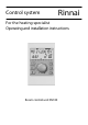
Control system Rinnai For the heating specialist Operating and installation instructions Room control unit RS100
Contents General safety instructions ...........................................................3 Safety measures for electric - compliant installation .................3 Installation of the room control unit .............................................5 Mounting location .................................................................................................5 Mounting instructions ...........................................................................................5 Electrical connection ..
General safety instructions 2. When installing the room control unit a minimum distance of 15.75 in (40 cm) must be maintained to other electrical utilities with electromagnetic emissions, such as power contactors, motors, transformers, dimmer switches, microwave ovens and televisions, loudspeakers, computers, mobile phones etc. All electrical connections and safety measures have to be carried out by a specialist in due consideration of valid standards as well as the local regulations.
6. The outside sensor may not be installed close to transmitting or receiving equipment (on garage walls close to receivers for radio-controlled garage door openers, amateur radio antennas, radio controlled alert systems or close to large scale radio transmission equipment). 4. It is suggested to use a shielded cable for all installations. 5. The shielding of the cable has to be connected with earth potential, i.e. boiler covering, connecting terminals for earth potential etc.
Installation of the room control unit – on non-insulated outside walls – in corners or wall recesses, shelves or behind curtains (insufficient ventilation) – close to doors of unheated rooms (influence of low temperatures) – on unsealed flush-type boxes (influence of external low temperatures due to the chimney effect of installation tubes) – in rooms with radiators controlled by thermostatic valves (mutual influence).
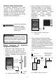
Electrical connection Electrical boiler The 2-strand data bus cable is connected to terminals A and B of the 2-pole terminal strip on the bottom plate. connection at The electrical connection depends on the type and version of the respective heating generator and takes place directly at the terminals A and B in the corresponding boiler control or interface. Further detailed information can be found in the documentation for the corresponding boiler.
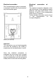
Accessories 5– Establish the electrical connection. To this end, preferably use a 2-strand cable with a minimum cross-section of 2 1 mm (18 AWG). The connection is made at the 2 screw terminals inside the sensor case and may be interchanged. 6– Attach the lid again and screw it firmly onto the base. Ensure correct fit of sealing ring.
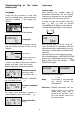
Commissioning of control unit the room Code input Installer code After entering the installer code all parameters determined for the heating specialist are released and can be edited in accordance with the system version. In order to enter the installer code, the keys and must be pressed simultaneously for approx. three seconds, until the code input appears in the display.
Alarm messages Alarm message register In order to be able to perform an exact diagnose in case of a problem the control system is equipped with a comprehensive fault alarm system. Depending on the nature of the fault a corresponding alarm message will appear in the display of the room control unit. The display and processing of logic alarms is deactivated in the factory and can be activated in the SYSTEM level by enabling Parameter 13 (= Logic alarm).
Site information A - Site and system temperatures If set value is displayed in the following table in the category "display value", it will appear when the rotary pushbutton is pushed. The following displays only appear under the specified display conditions. After accessing the information level using the , all available site- and information key system temperatures can be requested one by one by turning the rotary pushbutton clockwise or counter-clockwise.
Parameter synoptic Hold rotary push-button pressed for approx. 3 seconds - automatic call of time programs Select required level via rotary push-button and confirm, enter code if necessary 5 TIME PROGRAM CONTROL MODE See instructions SUMMER (switch-off) Output HC System frost protection DHW max. limit 6 HEAT.
Overview of installer parameters and adjustment options HYDRAULIC Level 02 05 Designation Function assignment of output for DHW-loading pump Function assignment of output for unmixed circuit pump Setting range / Setting values OFF No function 1 DHW-loading pump OFF 2 6 No function Unmixed circuit pump Constant control unit Individual setting Parameter Fact.
24 Fahrenheit range 27* Alarm messages system handling Automatic boiler control 28 Alarm message memory 2 OFF, ON OFF 1 2 3 Shown on display screen only Message from system interlocks Messages from interlocks and blockages into the system Message from interlocks, blockages and warnings into the system 4 OFF OFF, ON in dependence on access code only to released parameters * Function dependent upon support from boiler control system RESET OFF Reset to factory values – Designation DHW NIGHT
Adaptation heating curve OFF, ON (not during HC = constant control) OFF Inrush optimization OFF, 1 ... 16 h OFF 07 Heating limit OFF, 0,5...40,0 K (not during HC= constant contr.) OFF 08 Room frost protection temperat ure 5 ... 30 °C 10 °C 09 Room thermostat function OFF, 0.5 ... 5 K OFF 11 Constant control unit 10 ... 95°C (only if Par. 05 – Hydraulic =6) 20 °C 05 06 10 °C ... setting Maximum temperature limit (Parameter 13) Minimum temperature limit (Parameter 12) ...
ALARM 2 Level (..C..)* Designation Setting range / Setting values Individual setting Parameter Factory preset In this level up to 20 alarm messages can be stored, these are permanently updated.
Notes 100000157 16 9/2009