Owner’s Operation and Installation Manual for the EX17C (RHFE-434FTA) EX22C (RHFE-559FTA) Energysaver® Gas Direct Vent Wall Furnace Table of Contents .......................... 2 Consumer Safety Information ....... 3 Specifications ................................ 4 Operating Instructions ................... 6 Installation Instructions................ 15 Adjust Gas Pressure Settings ..... 28 Consumer Support ...................... 44 French Version ............................
This appliance may be installed as an OEM installation in a manufactured home (USA only) or mobile home and must be installed in accordance with the manufacturer’s instructions and the Manufactured Home construction and Safety Standard, Title 24 CFR, Part 3280, in the United States, or the Mobile Home Standard, CAN/CSA Z240 MH Series, in Canada. This appliance may be installed in an aftermarket, permanently located, manufactured home (USA only) or mobile home, where not prohibited by local codes.
Consumer Safety Information Safety Definitions This is the safety alert symbol. This symbol alerts you to potential hazards that can kill or hurt you and others. DANGER Indicates an imminently hazardous situation which, if not avoided, will result in death or serious injury. WARNING Indicates a potentially hazardous situation which, if not avoided, could result in death or serious injury.
Safety Features Overheat: The appliance will automatically shut down when the appliance exceeds a predetermined temperature. Power Surge Fuse: A glass fuse on the PC board protects against overcurrent. If the fuse blows then all indicator lamps will be off. Flame Failure: The appliance will automatically shut down if the burner flame is extinguished. Spark Detector: The appliance automatically shuts down if there is an abnormal spark at ignition.
Appliance Specifications Natural Gas Propane Gas Minimum supply gas pressure 3.5 in (89 mm) W.C. 8.0 in (203 mm) W.C. Maximum supply gas pressure 10.5 in (267 mm) W.C. 13.0 in (330 mm) W.C.
Operating Instructions Getting to Know your New Heating Appliance CONTROL PANEL WARM AIR OUTLET HUMIDIFIER REMOVE BOTTOM COVER AND PULL OUT TO REFILL RATING PLATE MODEL NUMBER, SERIAL NUMBER, GAS TYPE, ETC.
Control Panel Sensible Temperature Control The sensible temperature control feature allows comfortable heating which matches the conditions in the room. Based on the information collected by the room temperature thermistor when the heating starts, the heating capacity is automatically adjusted to achieve a comfortable heating effect and to reach the temperature setting quickly. Occasionally, the room temperature may briefly exceed the temperature setting due to the layout of the room or heating area.
Setting the Clock 1. Press the “Set Times” button. 2. The light next to “Clock” should be lit. Press the up and down arrows to set the time. Holding down either of the arrow keys will change the time more quickly. 3. Press the “Set Times” button until none of the time options are lit up. Operating the Heater Manually 1. Turn the heater on by pressing the “ON/OFF” button. 2. Press the up or down arrows to set the temperature. The left side of the display shows the temperature setting.
Override Function This function is used only when the heater is in Timer operation. It allows you to “override” the reset timer setting until the beginning of the next Timer period. For example, if the heater is ON, pressing the “Override” button will turn the heater OFF until the next period. If the heater is OFF, pressing the “Override” button will turn the heater ON, and allow you to select a temperature setting, until the next period.
Set back This function allows a minimum room temperature to be pre-set, between 38ºF and 78ºF (in 2ºF increments). This temperature should be set below the room temperature setting. The default setting is 60ºF. Once the Set back function is selected the appliance will start heating whenever the room temperature falls below the selected temperature, regardless of timer or manual settings. Follow these steps to set and operate the Set back feature: 1. Make sure the heater is turned OFF. 2.
Care and Maintenance Maintenance Filters All maintenance and service are to be performed by a qualified service technician, preferably one who has attended Rinnai service training classes on the Direct Vent products. Dirty filters reduce the air flow and the appliance’s ability to produce heat. The filters should be cleaned frequently during the heating season. The appliance should be inspected annually by a qualified service technician.
Before Making a Service Call Before making a service call please check the following: At Ignition: Heater does not operate. Is the heater plugged in? Have the fuses or breaker blown at the fuse box / breaker panel? Is there a power failure? Is the air filter blocked? Is anything blocking the outlet for the hot air? Is the flue blocked? Warm air does not flow when the burner lights. The fan is started automatically after a short delay.
Fault Codes If there is a malfunction the appliance may shut down as a safety precaution and display a fault code to assist in diagnosing the problem. The fault code will flash in the display on the control panel. When making a service call, this code will assist with diagnosing the fault. CODE DISPLAYED You may be able to clear the fault code by turning the heater off and then on again.
Restart Function If there is a power failure while the appliance is on, then the appliance will start automatically when the power is restored. If the appliance fails to ignite, the appliance will attempt ignition after 1 hour. The “Ignition Failure” fault code, 11, will appear during that hour and disappears after a successful ignition. If ignition fails again, then the fault code will remain and another attempt to ignite will occur in 1 hour. The fault code is not stored in the fault code history.
Installation Instructions General Instructions Rinnai suggests that a dedicated electrical circuit with a 120V AC, 60 Hz, 10 amp power source be used. WARNING Do not use substitute materials. Use only parts certified with the appliance. NOTICE If installation is at a location above 2001 ft (611 m), then follow the Adjust Gas Pressure Settings section. If installation is at or below 2000 ft (610 m) then the pressure settings do not need to be adjusted.
Gas Connection The gas supply line shall be gas tight, sized and so installed as to provide a supply of a gas sufficient to meet the maximum demand of the heater without loss of pressure. Check the gas supply pressure immediately upstream at a location provided by the gas company. Supplied gas pressure must be within the limits shown in the Specifications section. A shut off valve and appliance connector valve should be installed in the upstream of the gas line to permit servicing.
Dimensions 22.9 in (582 mm) 29.9 in (760 mm) 10.1 in 257 mm 6.8 in 172 mm 3.3 in 85 mm NOTICE A full size template is provided on the cardboard packaging. DO NOT DISCARD until installation is completed.
D E L SNOW B Clearance in Ref.
Flue Terminal Clearances Ref A Description Clearance above grade, veranda, porch, deck, or balcony.
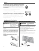
Installation Parts The following items are included with the appliance: Flue Manifold 1 Spare rubber seal (‘A’ Flue units only) “A” “A” Vent Vent Kit, Kit, FOT-151 1 (For weatherboard installations) Back Spacer Set Screw (M4) Wall Bracket 1 Ring 1 Manual Valve Set 1 1 Owner’s Manual Screw (M4) Pipe Stopper A For Back Spacer Set For Spacer Bracket Plastic tie for air inlet 1 1 Plastic tie* (L=250mm) 1 4 Screw (M4) 4 1 Wood Screw (M4.
8 7/16" (214 mm) R m 6 20 (R Ensure that there are no gas or water lines, or electrical circuits in the wall location where the flue hole is to be drilled. Drill the flue hole using a 3 1/8 inch (80 mm) drill. The center of the hole must be located anywhere within the shaded area, unless extension kits are used. See diagram. For weatherboard walls, drill through the center of the weatherboard from the outside first and then through the plasterboard. A template is provided.
Flue Manifold Installation The flue manifold must exhaust to the outside. Do not exhaust into other rooms. The flue manifold is not designed to be positioned under floors or below the heater. This appliance can only be used with one of the five types of Rinnai flue kits. The flue kits and their dimensions are listed on the previous page. Refer to the Flue Terminal Clearances section. The termination cannot be vertical. 1.
Flue Manifold Installation 4. Install the Terminal Check that the terminal seal is in place. For weatherboard walls, add the second seal next to the terminal seal to compensate for weather board angle. Terminal seal From the outside insert the terminal into the sleeve with the marking “TOP” at the top. The left hand side locking tie should be marked “LEFT”. Terminal Locking tie 5. Lock the ties Pulling hard on the left and right hand ties, clip the ties over the notches inside the sleeve.
Extension Kit Installation If necessary, extension kits are available to extend the exhaust line and air intake hose between the manifold and the appliance. INCORRECT Too many bends (limit is 2) Air intake hose is above exhaust pipe (1) The maximum vent length is 13 feet (4 m) with 2 bends. The bent pipe attached to the appliance does not count toward the max limit of 2 bends. (2) Maximum vertical length allowed is 10 feet (3 m).
Extension Kit Installation CAUTION Clearances Use the pipe stoppers, connectors, clamps, and screws according to these instructions in order to ensure no leakage of exhaust gases. exhaust pipe to combustibles 1 inch (25.4 mm) exhaust pipe to non-combustibles zero Clamps Exhaust pipe Both the exhaust line and air intake hose are supported by clamps which are attached to the wall. A wall fixture can be used to offset the clamp from the wall. Use Screw B to attach the wall fixture to the wall.
Extension Kit Installation Extension Kits and Parts EXHAUST PIPE (ADJUSTABLE) BENT ELBOW HOSE JOINT LONG BENT ELBOW PIPE CLAMP Item EXHAUST PIPE (NON ADJUSTABLE) WALL-FIXTURE Description PIPE STOPPER A 1 Exhaust Pipe (adjustable) 11.4-20.3 in (290-515 mm) TOP STOPPER 1 Exhaust Pipe (adjustable) 21.0-39.6 in (533-1005 mm) FOT-219 FOT-220 FOT-221 SCREW B 1 1 FOT-158 FOT-190 1 2 Exhaust Pipe - 40 in (1016 mm) 3 Air Intake Hose - 29.5 in (750 mm); 1.5 in (38 mm) inner dia.
Connecting the Appliance a 1. Attach the air inlet hose to the flue manifold on either inlet position “a” or “b”. The plastic tie should be tight over the sleeve. b The unused inlet is plugged with the rubber cap supplied on the manifold. 2. Connect the flue elbow to the manifold while moving the appliance into position. 3. Fit the pipe stopper over the connection between the flue elbow and the manifold. Engage the hook and rotate it until it snaps against the body of the clamp.
Adjust Gas Pressure Settings CAUTION Do not touch any other areas on the PC board besides the switches while power is supplied to the appliance. Parts of the PC board are supplied with 120 volts AC. Pressure Point CAUTION Do not touch the areas at or near the exhaust. These areas become very hot and could cause burns. Test Switch 1. Turn off the gas and the power supply. 2. Remove the 5 screws that hold the louver assembly and front panel. Lift the panel straight up and then remove it. PC Board 3.
Adjust Gas Pressure Settings 6. Press the test switch twice to record the gas type code into memory. . 7. Press the ON/OFF button to operate the appliance. 8. Press the test switch twice. The LED will display “PL” indicating low fire mode. 9. Compare the pressure reading on the manometer to the desired manifold test pressure (low) for your gas type and altitude. If necessary adjust the low fire pressure using the ▲ and ▼ buttons. 10. Press the test switch.
Operating Instructions FOR YOUR SAFETY READ BEFORE OPERATING WARNING If you do not follow these instructions exactly, a fire or explosion may result causing property damage, personal injury or loss of life. A. This appliance does not have a pilot. It is equipped with an ignition device which automatically lights the burner. Do not try to light the burner by hand. B. BEFORE OPERATING smell all around the appliance area for gas.
Cut-Away Diagram Rinnai Corporation EX17C / EX22C Manual 31
Wiring Diagram CAUTION Label all wires prior to disconnection when servicing controls. Wiring errors can cause improper and dangerous operation. If any of the original wire as supplied with the appliance must be replaced, it must be replaced with type 18 AWG wire or its equivalent. CODE COLOR bk black MARK PART NAME MARK PART NAME bl blue MS MAIN SWITCH OH.TH OVER HEAT THERMISTOR gr green R.
Rinnai Corporation EX17C / EX22C Manual OVER HEAT SWITCH 1, 2 OHS1, 2 FM THERMISTOR THERMAL FUSE FUSE R.TH TF F ER FCC MB CPU TRANSFORMER FLAME ROD PRESSURE SENSOR TR FR PS CONVECTION FAN BL MODULATING SOLENOID VALVE POV CF MAIN SOLENOID VALVE 1, 2 SV1, 2 ELECTRODE CENTRAL PROCESSING UNIT MAIN BURNER FAN CONTROL CIRCUIT COMBUSTION FAN MOTOR SPARKER SP CONVECTION FAN MOTOR OVER HEAT THERMISTOR OH.
Parts List For replacement parts call Rinnai at 1-800-621-9419.
Parts List Rinnai Corporation EX17C / EX22C Manual 35
Parts List 36 Rinnai Corporation EX17C / EX22C Manual
Parts List Rinnai Corporation EX17C / EX22C Manual 37
Parts List 38 Rinnai Corporation EX17C / EX22C Manual
Parts List Rinnai Corporation EX17C / EX22C Manual 39
Parts List (Liste de pieces) Pour les pièces de rechange appelez Rinnai au 1-800-621-9419.
Parts List (Liste de pieces) No 047 048 100 101 102 103 104 105 106 107 108 109 110 111 112 113 114 115 116 117 118 119 120 120 121 122 123 124 125 126 127 128 129 130 131 132 133 134 135 136 137 138 139 140 Name Spacer Bracket ON-OFF Valve Assy Heat Exchanger Assy Fixing Plate Combustion Chamber Fixer OHS Fixer Burner Box Flange Board Seal Plate B Nom support espaceur ensemble de vanne M/A ensemble d’échangeur thermique plaque de fixation fixation de chambre de combustion fixation interrupteur de surchau
Parts List (Liste de pieces) No 141 EX22C 1 EX22C-W (white) 1 EX17C 1 208000013 CP-30310 308F-8273 208000043 RHF300-200-E 302F-1103X04 302F-1206 431F-1900 208000044 305F-0017 RC-329-1033 208000017 208000045 1004F-2052-3 1 6 6 1 1 1 1 1 1 1 1 1 1 1 1 6 6 1 1 1 1 1 1 1 1 1 1 1 1 6 6 1 1 1 1 1 1 1 1 1 1 1 208000046 556F-259-2 208000047 209000126 1 1 1 1 1 1 1 1 1 1 1 1 208000048 208000049 RC-223-74 556F-309 209000127 209000128 308F-313 CP-90125-2 CP-90107-25 209000129 1 1 1 1 1 1 1 3 2 1 1 1 1 1
Parts List (Liste de pieces) No Name 710 711 712 713 714 715 716 717 800 801 Overheat Switch Overheat Switch Igniter Sleeve FR Lead TF Harness Indicator Harness Pressure Sensor Water Line Label Operation Label 802 803 804 808 Power Supply Cord label Caution Label Caution Label Manual Nom interrupteur de surchauffe interrupteur de surchauffe allumeur manchon liaison FR toron - TF toron d'indicateur détecteur de pression ligne de flottaison étiquette étiquette d'opération étiquette de corde d'alimentati
Consumer Support Warranty Information The installer is responsible for your heater’s correct installation. Please complete the information below to keep for your records: Purchased from: _________________________________________________________________ Address: _____________________________ Phone: _________________________________ _____________________________ Date of Purchase: __________________________________ Model No.: ________________________________________ Serial No.
Limited Warranty - continued Replacement of the product may be authorized by Rinnai only. Rinnai does not authorize any person or company to assume for it any obligation or liability in connection with the replacement of the product. If Rinnai determines that repair of a product is not possible, Rinnai will replace the product with a comparable product at Rinnai’s discretion.
State Regulations NOTICE BEFORE INSTALLATION Rinnai direct-vent appliance must be installed by a state qualified or licensed contractor and a properly trained Rinnai Installer. If you are not properly trained, you must not install this unit. IMPORTANT: In the State of Massachusetts (248 CMR 4.00 & 5.
Manuel d’installation et d’utilisation pour EX17C (RHFE-434FTA) EX22C (RHFE-559FTA) Energysaver® Appareils de chauffage à gaz muraux à ventilation directe Table des matières ................. 48 Sécurité du consommateur ... 49 Spécifications ......................... 50 Instructions d’utilisation .......... 52 Instructions d’installation ........ 61 Service à la clientèle .............. 80 Enregistrer votre produit à www.rinnairegistration.
Cet appareil peut être installé comme du matériel d’origine dans une maison préfabriquée (É.-U. seulement) ou dans une maiason mobile et doit être installé selon les instructions du fabricant et conformément à la norme Manufactured Home Construction and Safety Standard, Title 24 CFR, Part 3280 ou à la norme CAN/CSA-Z240 Série MM, Maisons mobiles.
Sécurité du consommateur Définitions de sécurité Ceci est un symbole relatif à la sécurité. Il vous prévient de dangers potentiels qui peuvent blesser ou tuer, vous-même et les autres. DANGER Indication d’une situation imminente dangereuse, qui, si elle n’est pas évitée, peut entraîner des blessures graves voire mortelles. AVERTISSEMENT Indication d’une situation potentiellement dangereuse, qui, si elle n’est pas évitée, peut entraîner des blessures graves voire mortelles.
Dispositifs de sécurité Surchauffe : l’appareil se coupe automatiquement quand il atteint une température limite prédéterminée. Défaut de flamme : L’appareil se coupe automatiquement si la flamme de son brûleur est éteinte. Coupure secteur : L’appareil coupe son arrivée de gaz s’il n’a plus d’alimentation secteur. Protection de surintensité : Un fusible en verre sur le circuit imprimé protège d’une surintensité. Quand ce fusible est grillé tous les voyants indicateurs sont éteints.
Spécifications de l’appareil Gaz naturel Gaz propane Pression d’alimentation en gaz min. 3.5 in (89 mm) W.C. 8.0 in (203 mm) W.C. Pression d’alimentation en gaz max. 10.5 in (267 mm) W.C. 13.0 in (330 mm) W.C.
Instructions d’utilisation Connaissance du nouveau chauffage AFFICHAGE SORTIE D’AIR CHAUD HUMIDIFICATEUR ÔTER LE COUVERCLE DU BAS ET LE TIRER POUR REGARNIR PLAQUE SIGNALÉTIQUE RÉFÉRENCE DE MODÈLE, N° DE SÉRIE, TYPE DE GAZ, ETC.
Panneau de commandes Contrôle de température Sur la base des informations collectées par la thermistance sur la température de la pièce quand le chauffage démarre, la capacité de chauffage est automatiquement ajustée pour produire un effet de réchauffement confortable et atteindre rapidement la température de consigne. De temps en temps la température ambiante peut dépasser brièvement la consigne du fait de la disposition de la pièce ou de la zone chauffée.
Mise à l’heure 1. Appuyez sur le bouton “Set Times”. 2. Le voyant près de “Clock” doit s'allumer. Actionnez un bouton de flèche montante ou descendante pour régler l'heure. Le maintien enfoncé d'une de ces touches fait défiler l'heure plus rapidement. 3. Appuyez de nouveau sur le bouton “Set Times” jusqu'à ce qu'aucune des options de changement de paramètres d'heure ne soit allumée. Utilisation manuelle du chauffage 1. Mettez le chauffage en marche en actionnant une fois son bouton “ON/OFF”. 2.
Fonction de surpassement Cette fonction est utilisée uniquement quand le chauffage est en fonctionnement par minuterie. Il vous permet de “surpasser” l'action de la minuterie en cours jusqu'au démarrage de la suivante. Par exemple, si le chauffage était en marche (ON), l'appui sur le bouton “Override” va l'arrêter (OFF) jusqu'à la période suivante.
Programmation de température minimale Cette fonction permet de déterminer à l'avance une température minimale pour la pièce, à définir entre 38ºF et 78ºF (par incréments de 2ºF). Cette température doit être définie ci-dessous le réglage de la température de la pièce. La valeur par défaut est de 60ºF. Une fois que cette fonction a été activée, l'appareil commencera à chauffer dès que la température de la pièce tombe sous le seuil sélectionné, quels que soient les réglages par minuterie ou manuels.
Soins et entretien Entretien Filtres Toute intervention d’entretien et dépannage doit être effectuée par un technicien de service qualifié, qui de préférence a suivi des cours de service chez Rinnai sur ses produits à ventilation directe. Des filtres sales réduisent le flux d’air et la capacité de l’appareil à produire de la chaleur. Les filtres doivent être nettoyés fréquemment pendant la saison de chauffe.
Avant d’appeler pour de l’aide Avant de lancer un appel pour recevoir de l’assistance, vérifiez les points qui suivent : At Ignition: : À l’allumage Le chauffage Heater does ne notfonctionne operate. pas.
Codes de défauts En cas de dysfonctionnement, l’appareil peut se couper comme précaution de sécurité, elle affiche alors un code de défaut pour aider à diagnostiquer le problème. Ce code de défaut va clignoter à l’afficheur du panneau de commandes. Quand vous appelez pour une de mande d’intervention, donnez ce code qui aidera à cerner le défaut. CODE AFFICHÉ Vous pouvez peut-être éliminer le code de défaut en passant le chauffage sur arrêt puis en le remettant en marche.
Fonction de redémarrage Si il y a une panne de courant, tandis que l'appliance est sur, puis l'application démarre automatiquement lorsque l'alimentation est restaurée. Si l’appareil n’arrive pas à s’allumer, il essaiera de nouveau son allumage après 1 heure. Le code de défaut 11 “Panne d’allumage” apparaîtra durant ce délai. Si la nouvelle tentative réussit, ce code de défaut disparaitra de l’affichage, sinon il demeurera et une nouvelle tentative d’allumage se répétera une heure plus tard.
Instructions d’installation Instructions générales Cet appareil envoie un gros volume d’air chaud vers le AVERTISSEMENT N’utilisez pas de matériaux de substitution. N’utilisez que des pièces certifiées pour aller sur cet appareil. AVIS Si l’installation a lieu à une altitude qui dépasse les 2 001 pieds (611 m), reportez -vous au Ajustage et Reglage de la Presion de Gas.
Connexion de gaz La conduite d’arrivée de gaz doit être étanche, bien Vérifiez la pression d’alimentation en gaz immédiatement calibrée et installée de façon à fournir assez de gaz pour la demande maximale du chauffage sans perte de pression. Une vanne de coupure principale et une vanne à la connexion de l’appareil doivent être installés en amont de l’appareil sur la conduite d’alimentation pour permettre l’arrêt d’alimentation durant des interventions.
D E L B F des obstructions. Vérifiez en outre les règlements locaux.
Dégagements en sortie de cheminée (Suite) Réf. A Description Dégagement au-dessus de sol, véranda, porche, plate-forme ou balcon.
Dimensions 22.9 in (582 mm) 29.9 in (760 mm) 10.1 in 257 mm 6.8 in 172 mm 3.3 in 85 mm AVIS Un modèle de taille complète est fourni sur l'emballage en carton. NE JETEZ pas jusqu'à ce que l'installation est terminée.
Pièces d’installation Les articles suivants sont inclus avec l’appareil livré : Flue Manifol d fumée Collecteur de 1 SpaJoint re rucaoutchouc bber seal de rechange1 (‘A’ Flue units only) (appareils à ventilation « A » uniquement) Vent FOT-151 “A”“A” Vent Kit,Kit, FOT-151 (pour installations avec parement bois) (For weatherboard installations) Jeu Back Spacer d’espaceurs Setarrière Manuel d’utilisation Screw Vis (M4) 1 Fermeture Ring d’isolation 1 Manual Valve Vanne manuelle Set 1 Attache Plast
( 8 7/16" (214 mm) Vérifiez qu’il n’y a pas de conduites d’eau, gaz ou électricité caches là où il faut percer. Percez le trou de cheminée en utilisant un outil de coupe pour diamètre 80 mm (3-1/8 po). Le centre du trou doit être situé exactement au point spécifié. Reportez-vous au schéma. Trou de cheminée Flue Hole 3 1/8" (80 mm) Perçage du trou de cheminée Pour les murs avec parement bois, percez au centre du revêtement à partir de l’extérieur d’abord, puis au travers du placoplâtre.
Installation du collecteur de fumée Le collecteur de fumée doit sortir à l’extérieur. N’évacuez pas dans d’autres pièces. La cheminée n’est pas conçue pour être positionnée sous des planchers ou sous le chauffage. La terminaison ne peut pas être verticale. 1. L’appareil ne peut être utilisé qu’avec l’un des cinq types de kits de collecteurs de fumée de Rinnai. Ces kits et leurs dimensions sont listés dans la section des spécifications.
Installation du collecteur de fumée (Suite) 4. Installation de la terminaison Vérifiez que le joint de terminaison est en place. Pour les murs avec parement en bois, ajoutez le second joint près du joint de terminaisons pour compenser pour l’angle de parement. Joint de terminaison Depuis l’extérieur insérez la terminaison dans le manchon en gardant le marquage « TOP » vers le haut. Le blocage de côté gauche doit être repéré par « LEFT ». Terminaison Attache de blocage 5.
Installation du kit d’extension Si nécessaire, des kits d’extension sont disponibles pour prolonger la conduite d’évacuation et le tuyau d’admission d’air entre collecteur de fumée et appareil. (1) La longueur maximale évent est de 13 pieds (4 m) avec 2 plis. Le tuyau tordue relié au matériel ne compte pas dans la limite maximale de 2 plis. (2) La longueur verticale maximale permise est de 8 pieds (2,4 m). (3) Si l'extension est supérieure à 10 pieds (3 m), le condensat peut déborder le pan de condensation.
Installation du kit d’extension (Suite) ATTENTION Dégagements Utilisez arrêts de tuyau, connecteurs, colliers et vis en suivant ces instructions de façon à assurer l’absence de fuites de gaz d’évacuation.
Installation de kit d’extension Kits et pièces d’extension EXHAUST PIPE (ADJUSTABLE) TUYAU D’EXTENSION (RÉGLABLE) COUDEELBOW BENT COLLIER DE PIPE CLAMP TUYAUX EXHAUST PIPE (NON ADJUSTABLE) TUYAU D’EXTENSION (NON RÉGLABLE) COUDE LONG ELBOW LONG BENT HOSEDE JOINT JOINT TUYAUX DISPOSITIF MURAL WALL-FIXTURE Réf.
Branchement de l’appareil 1. a Fixez le tuyau d’arrivée d’air sur le collecteur de fumée sur les entrées « a » ou « b ». La cravate en plastique doit être serré sur la manche. b L’entrée non utilisée doit être fermée avec le bouchon en caoutchouc fourni avec le collecteur. 2. Branchez le coude de cheminée sur le collecteur tout en mettant l’appareil en place. 3. Adaptez la fermeture de tuyau sur le raccordement entre le coude de cheminée et le collecteur.
Ajustage et Reglage de la Presion de Gas ATTENTION Ne pas toucher aucuns autres secteurs sur le conseil de PC outre les commutateurs pendant que le pouvoir est fourni à l'appareil. Les parties du conseil de PC sont fournies avec 120 volts. Point de vérification du gaz ATTENTION Ne pas toucher les secteurs à ou près du panneau de verre ou près de l'échappement. Ces secteurs deviennent très chauds et pourrait causer des brûlures. Commutateur d’essai 1. Eteindre le gaz et le pouvoir fournit. 2.
Ajustage et Reglage de la Presion de Gas 6. Appuyer le commutateur d’essai deux fois pour entrer ce code dans la mémoire. 7. Appuyer l'interrupteur pour fonctionner l'appareil. 8. Appuyer le commutateur d’essai deux fois. Le MENE affichera « PL » indiquant le mode de feu faible. 9. Comparer la pression lisant sur le manomètre aux Données Techniques, le niveau bas de pression de test divers, pour le gaz étant utilisé. Si nécessaire ajuster la pression basse de feu utilisant le ▲ et ▼ boutons. 10.
Instructions de mise en œuvre À LIRE AVANT DE METTRE EN MARCHE, POUR VOTRE SÉCURITÉ AVERTISSEMENT Si vous ne suivez pas ces instructions à la lettre, il peut en résulter incendie ou explosion, entraînant dégâts et blessures sérieuses ou mortelles. A. Cet appareil ne comporte pas de veilleuse. Il est équipé d’un dispositif d’allumage qui allume automatiquement le brûleur. Ne tentez pas d’allumer le brûleur manuellement. B.
Rinnai Corporation EX17C / EX22C Manual TUBULURE BRÛLEUR SONDE DE PRESSION ÉLECTRODE PORT DE VUE DE FLAMME ÉLECTRODE DE DÉTECTION DE FLAMME VIDANGEZ LA CASSEROLE INTERRUPTEUR DE SURCHAUFFE THERMISTANCE DE SURCHAUFFE BAC D’HUMIDIFICATION INTERRUPTEUR DE SURCHAUFFE ENSEMBLE DE PERSIENNES FUSIBLE THERMIQUE ÉCHANGEUR THERMIQUE PANNEAU FRONTAL VENTILATEUR DE CONVECTION TRANSFORMATEUR ALLUMEUR PASSAGE CORDON D’ALIMENTATION SECTEUR THERMISTANCE INTERCONNEXION CARTE DE CIRCUIT IMPRIMÉ VENTILA
Schéma de câblage ATTENTION Étiquetez tous les fils avant les interventions de contrôle. Des erreurs de câblage peuvent causer un fonctionnement incorrect et dangereux. Vérifiez le bon fonctionnement après une intervention. MARQUAGE MS R.TH TF F ER POV NOM DE PIÈCE MARQUAGE COMMUTATEUR PRINCIPAL THERMISTANCE OH.TH OHS 1, 2 Si des fils d’origine livrés avec l’appareil ont besoin d’être remplacés, choisissez un fil de calibre 18 AWG ou équivalent.
Rinnai Corporation EX17C / EX22C Manual SP BL FCC MB CPU FUSIBLE ÉLECTRODE VANNE MODULATRICE TRANSFORMATEUR ÉLECTRODE DE DÉTECTION DE FLAMME DÉTECTEUR DE PRESSION VENTILATEUR DE CONVECTION F ER POV TR FR PS CF SV1, 2 FM FUSIBLE THERMIQUE OHS 1, 2 THERMISTANCE R.TH TF OH.
Service à la clientèle Informations de garantie L’installateur est responsable de l’installation correcte du chauffage.
Garantie limitée (Suite) Le remplacement du produit ne peut être autorisé que par Rinnai. La société Rinnai ne permet à aucune personne ou société d’assumer pour elle toute obligation ou responsabilité relative au remplacement d’un produit. Si Rinnai détermine que la réparation d’un produit n’est pas possible, Rinnai le remplacera avec un produit comparable, à sa discrétion.
Notes 82 Rinnai Corporation EX17C / EX22C Manual
Notes Rinnai Corporation EX17C / EX22C Manual 83
Rinnai’s other fine products Tankless Water Heaters • Residential and Commercial Applications • Continuous Hot Water • ENERGY STAR ® qualified models • Up to 9.8 GPM • Internal or External Installation • Digital Temperature Control Condensing Tankless Water Heaters • Residential and Commercial Applications • ENERGY STAR ® qualified models • Up to 0.