Owner’s Operation and Installation Manual for the ES38 (RHFE-1004RFA) Energysaver Gas Direct Vent Wall Furnace Table of Contents ........... 2 Safety Information .......... 3 Operating Instructions .... 6 Care and Maintenance ... 10 Fault Codes .................... 12 Installation Instructions ... 14 Parts List ........................ 32 Consumer Support .........
This appliance may be installed as an OEM installation in a manufactured home (USA only) or mobile home and must be installed in accordance with the manufacturer’s instructions and the Manufactured Home construction and Safety Standard, Title 24 CFR, Part 3280, in the United States, or the Mobile Home Standard, CAN/CSA Z240 MH Series, in Canada. This appliance is only for use with types of gas indicated on the rating plate. A conversion kit is supplied with the appliance.
Consumer Safety Information Safety Definitions This is the safety alert symbol. This symbol alerts you to potential hazards that can kill or hurt you and others. DANGER Indicates an imminently hazardous situation which, if not avoided, will result in death or serious injury. WARNING Indicates a potentially hazardous situation which, if not avoided, could result in death or serious injury.
Safety Features • Overheat: The appliance will automatically shut down when the appliance exceeds a predetermined temperature. • Power Surge Fuse: A glass fuse on the PC board protects against overcurrent. If the fuse blows then all indicator lamps will be off. • Flame Failure: The appliance will automatically shut down if the burner flame is extinguished. • Spark Detector: The appliance automatically shuts down if there is an abnormal spark at ignition.
Appliance Specifications Natural Gas Propane Gas Minimum supply gas pressure 5.0 in (127 mm) W.C. 11.0 in (280 mm) W.C. Maximum supply gas pressure 10.5 in (267 mm) W.C. 13.0 in (330 mm) W.C. BTU/hour input Low 10,500 High 38,400 Low 10,500 High 36,500 BTU/hour output Low 8,400 High 30,720 Low 8,400 High 29,200 Features • Restarts automatically when ignition or combustion fails.
Operating Instructions Getting to know your new heating appliance 6 Rinnai Corporation ES38 Manual
Control Panel All buttons beep when operated. TEMPERATURE DISPLAY SHOWS EITHER THE TEMPERATURE OR CODED ERROR MESSAGES. ON/OFF BUTTON Easy operation One touch ignition 〈CONTROL PANEL 〉 Set Temp Room Temp Economy Temp Control ON/OFF Function Lock FILTER LAMP Flashes when filter is dirty. TEMPERATURE BUTTONS " " adjust temp. to lower setting. " " adjust temp. to a higher setting. > FUNCTION LOCK Lamp is "green" when this feature is on.
Operating the Heater Adjusting the Temperature Turning the heater ON When you press and release the ON/OFF button, the Temperature Level lamps will illuminate, the combustion fan will begin to run, and the spark will ignite the main burner. Set Temp Room Temp ON/OFF Temp Control This heater has an automatic ignition system. When the main burner has lit, the combustion lamp will glow red, and the spark will stop.
Operating the Heater Lock Sensible Temperature Control This feature locks the buttons to prevent unintended operation. The sensible temperature control feature allows comfortable heating which matches the conditions in the room. Temp Control Press the up and down buttons to activate and the lamp Function Lock will glow. Pressing and holding the up and down buttons for two seconds will disengage the Lock.
Care and Maintenance Maintenance Filters All maintenance and service are to be performed by a qualified service technician, preferably one who has attended Rinnai service training classes on the Direct Vent products. Dirty filters reduce the air flow and the appliance’s ability to produce heat. The filters should be cleaned frequently during the heating season. If the filters become blocked the filter indicator lamp will flash and the appliance will beep.
Before Making a Service Call Before making a service call please check the following: At Ignition: Heater does not operate. Is the heater plugged in? Have the fuses or breaker blown at the fuse box / breaker panel? Is there a power failure? Is the air filter blocked? Is anything blocking the outlet for the hot air? Is the flue blocked? Warm air does not flow when the burner lights. The fan is started automatically after a short delay.
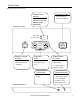
Fault Codes If there is a malfunction the appliance may shut down as a safety precaution and display a fault code to assist in diagnosing the problem. The fault code will flash in the display on the control panel. When making a service call, this code will assist with diagnosing the fault. CODE DISPLAYED You may be able to clear the fault code by turning the heater off and then on again.
Restart Function If the appliance fails to ignite, the appliance will attempt ignition after 1 hour. The “Ignition Failure” fault code, 11, will appear during that hour and disappears after a successful ignition. If ignition fails again, then the fault code will remain and another attempt to ignite will occur in 1 hour. The fault code is not stored in the fault code history. If the flame is extinguished during forced combustion then the appliance will attempt ignition after 1 hour.
Installation Instructions General Instructions WARNING Do not use substitute materials. Use only parts certified with the appliance. • A qualified service technician should install the appliance and inspect it before use. • If you move, check the gas type in your new area. The local gas authority will be able to advise on local regulations. • This appliance discharges a large volume of warm air next to the floor.
Gas Connection WARNING When connecting the gas valve or other gas components in the gas line, use a backup wrench to ensure the connection is gas tight. • The gas supply line shall be gas tight, sized and so installed as to provide a supply of a gas sufficient to meet the maximum demand of the heater without loss of pressure. • A shut off valve and appliance connector valve should be installed in the upstream of the gas line to permit servicing.
D E L SNOW B Clearance in Ref.
* 12 inches (30 cm) to nonflammables 2 24 inches (60 cm) to flammables 2 * * 6 feet (1.83 m) 7 feet (2.
Dimensions inches (mm) 14 1/16" (357.
Installation Parts The following items are included with the appliance: Flue Manifold .......................1 Spare rubber seal...........................
Drilling Flue Hole Flue Hole 3 1/8" (80 mm) Ensure that there are no gas or water lines, or electrical circuits in the wall location where the flue hole is to be drilled. Drill the flue hole using a 3 1/8 inch (80 mm) drill. A template is provided. The center of the hole must be located anywhere within the shaded area, unless extension kits are used. See the dimensions diagram. For weatherboard walls, drill through the center of the weatherboard from the outside first and then through the plasterboard.
Flue Manifold Installation • The flue manifold must exhaust to the outside. Do not exhaust into other rooms. • The flue manifold is not designed to be positioned under floors or below the heater. • This appliance can only be used with one of the five types of Rinnai flue kits. The flue kits and their dimensions are listed on the previous page. • Refer to the Flue Terminal Clearances section. • The termination cannot be vertical. 1.
Flue Manifold Installation 4.Install the Terminal Check that the terminal seal is in place. For weatherboard walls, add the second seal next to the terminal seal to compensate for weather board angle. Terminal seal From the outside insert the terminal into the sleeve with the marking “TOP” at the top. The left hand side locking tie should be marked “LEFT”. Terminal Locking tie 6. Lock the ties Pulling hard on the left and right hand ties, clip the ties over the notches inside the sleeve.
Extension Kit Installation If necessary, extension kits are available to extend the exhaust line and air intake hose between the manifold and the appliance. The maximum vent length is 13 feet (4 m) with 2 bends. The bent pipe attached to the appliance does not count toward the max limit of 2 bends. Any length (horizontal and vertical) in excess of 8 feet (2.4 m) must be sloped 3° downward toward the flue manifold to allow condensate to drain to the outside.
Extension Kit Installation CAUTION Clearances Use the pipe stoppers, connectors, clamps, and screws according to these instructions in order to ensure no leakage of exhaust gases. exhaust pipe to combustibles 1 inch (25.4 mm) exhaust pipe to non-combustibles zero Exhaust pipe Clamps Exhaust pipe Both the exhaust line and air intake hose are supported by clamps which are attached to the wall. A wall fixture can be used to offset the clamp from the wall.
Extension Kit Installation A B 1 Extension Kits and Parts FOT-102(11.4-20.3 inch) FOT-103(21.0-39.6 inch) EXHAUST PIPE PIPE STOPPER A 7 PIPE STOPPER B A FOT-102(29.5 inch) B FOT-103(49.2 inch) C FOT-114(90.6 inch) PIPE CLAMP 12 SCREW A 10 WALL-FIXTURE 13 SCREW B AIR INTAKE HOSE 8 4 9 EXHAUST PIPE(STRAIGHT) 40 inch 2 3 6 BENT ELBOW 5 TOP STOPPER 11 14 NUT O RING HOSE JOINT Item Description Part No. FOT-102 FOT-103 FOT-114 1 Exhaust Pipe (adjustable) 11.4-20.
Connecting the Appliance 1. Attach flue adapter to the flue manifold with pipe stopper S. Pipe stopper S Flue Adapter Plastic tie Flue Manifold 2. Attach the air inlet hose to the flue manifold. Secure with plastic tie. The unused inlet is plugged with the rubber cap supplied on the manifold. Inlet elbow Inlet hose 3. Connect the vent sliding tube with pipe stopper S and E. The sliding tube should not be extended beyond the red line.
Operating Instructions FOR YOUR SAFETY READ BEFORE OPERATING WARNING If you do not follow these instructions exactly, a fire or explosion may result causing property damage, personal injury or loss of life. A. This appliance does not have a pilot. It is equipped with an ignition device which automatically lights the burner. Do not try to light the burner by hand. B. BEFORE OPERATING smell all around the appliance area for gas.
Cut-Away Diagram 28 Rinnai Corporation ES38 Manual
Wiring Diagram CAUTION Label all wires prior to disconnection when servicing controls. Wiring errors can cause improper and dangerous operation. MARK MS R.TH TF1 ~3 F ER POV TR FR1 ~3 PARTS NAME MAIN SWITCH THERMISTOR THERMAL FUSE FUSE ELECTRODE MODULATING SOLENOID VALVE TRANSFORMER FLAME ROD 1 ~3 If any of the original wire as supplied with the appliance must be replaced, it must be replaced with type 18 AWG wire or its equivalent. MARK OH.
Ladder Diagram 30 Rinnai Corporation ES38 Manual
Parts List For replacement parts call Rinnai at 1-800-621-9419.
Parts List For replacement parts call Rinnai at 1-800-621-9419.
Parts List For replacement parts call Rinnai at 1-800-621-9419.
Parts List For replacement parts call Rinnai at 1-800-621-9419.
Parts List For replacement parts call Rinnai at 1-800-621-9419.
Parts List For replacement parts call Rinnai at 1-800-621-9419.
Parts List For replacement parts call Rinnai at 1-800-621-9419.
Parts List QTY ITEM 001 002 003 004 005 006 007 008 009 010 011 012 013 014 015 016 017 019 020 021 022 024 025 026 027 100 101 102 PART NUMBER PART NAME 1001F-073-9 1001F-073-4 1004F-2071-6 1004F-2071-3 1004F-2073-10 1004F-2073-6 556F-558-2 ZUAA02SZ 1001F-1514-2 1001F-1514-3 1001F-160-9 1001F-160-5 1004F-2080 1004F-2087 1001F-084-2 1001F-084-3 1001F-163-2 1001F-1323 1001F-162-7 1001F-162-4 1001F-164-4 1001F-1322 1001F-078 551F-015 RHF300-185-1 1001F-1410-2 1001F-1410-9 1001F-1411-4 1001F-1411-5 1001F-16
Parts List QTY ITEM 112 113 114 115 116 117 118 119 120 121 122 123 124 126 127 129 137 138 139 140 141 142 143 144 147 148 149 150 151 152 153 154 155 157 158 159 160 161 162 163 164 165 PART NUMBER PART NAME RHF250-076 1004F-2031 1004F-2036 1001F-042 1001F-041 1004F-2066 1004F-2065 1004F-2064 M10B-4-8 1001F-101-2 CP-30488 1004F-2030 RHFE1004-0130 1001F-008-2 1001F-106-1 BRR37-244 1001F-138-2 RHF1000-167 300FT-14 300FT-15 1004F-2013 1001F-115 1004F-2048 1001F-142-2 1001F-143 1001F-169 1001F-021-1 1001F-
Parts List QTY ITEM PART NUMBER PART NAME 181 192 400 401 402 403 404 405 406 407 408 409 410 411 412 413 414 415 416 417 419 420 421 422 423 424 425 426 427 430 431 432 433 435 436 700 CAP BUSH RE-INFORCED BOARD REAR PANEL ASS’Y FRAME LEFT ASS’Y FRAME RIGHT ASS’Y WARM AIR SEAL PACKING CONVECTION FAN SUPPORT B TOP PANEL SUPPORT FRAME CORNER TOP PANEL REINFORCEMENT FRAME CORNER ASS’Y CONVECTION MOTOR CONVECTION MOTOR BRACKET CONVECTION FAN A CONVECTION FAN B FAN CASING ASS’Y BELL MOUTH HEAT SHIELD BOARD B
Parts List QTY ITEM PART NUMBER PART NAME 800 801 801 802 803 804 805 806 806 807 808 809 810 810 811 812 813 814 850 851 852 853 853 856 901 902 903 904 905 906 907 908 909 910 911 912 913 914 CP-74167-28 CP-74168-27 CP-74168-28 1004F-2093 1001F-1651 556F-2065 1001F-1656 431F-1840 431F-1841 1001F-1654 CP-72062B-2 431F-1860 431F-1862 431F-1863 431F-1830 CP-71747-2 CP-74177-5 CP-74178-5 RHFE1004-0110 RHFE1004-0111 1004F-2040 1004F-2095-3 1004F-2095-4 CP-30324 ZBA0408SC ZBA0408SZ CP-30421-1 ZBA0412SZ ZBB04
Consumer Support Warranty Information The installer is responsible for your heater’s correct installation. Please complete the information below to keep for your records: Purchased from: _________________________________________________________________ Address: _____________________________ Phone: _________________________________ _____________________________ Date of Purchase: __________________________________ Model No.: ________________________________________ Serial No.
Limited Warranty - continued Replacement of the product may be authorized by Rinnai only. Rinnai does not authorize any person or company to assume for it any obligation or liability in connection with the replacement of the product. If Rinnai determines that repair of a product is not possible, Rinnai will replace the product with a comparable product at Rinnai’s discretion.
Rinnai’s other fine products Rinnai America Corporation 103 International Drive Peachtree City, GA 30269 TOLL FREE: 1-800-621-9419 www.rinnai.us Tankless Water Heaters • • • • • • • • Residential and Commercial Applications Continuous Hot Water Up to 9.