Gas Fan Convec on Heater Installa on and Opera on Manual FC510 ................... (RCE‐391A‐H) FC824 ................... (RCE‐691TA‐H) Installer: Leave this manual with the appliance. Consumer: Retain this manual for future reference. ANSI Z21.11.2 WARNING If the informa on in these instruc ons is not followed exactly, a fire or explosion may result causing property damage, personal injury or loss of life.
Table of Contents Table of Contents ..................................................... 2 Safety Defini ons ..................................................... 2 Safety Behaviors and Prac ces for the Consumer and Installer ............................................ 3 Installa on Instruc ons ....................................... 4 Installer Qualifica ons ....................................... 4 General Instruc ons .......................................... 4 Determine Installa on Loca on ...........
Safety Behaviors and Prac ces for the Consumer and Installer WARNING Before opera ng, smell all around the appliance area for gas. Be sure to smell next to the floor because some gas is heavier than air and will se le on the floor. Ensure the room is sufficiently ven lated. Consult your Early signs of carbon monoxide poisoning resemble the flu, with headaches, dizziness, or nausea. If you have these signs, the heater may not be working properly. Get fresh air at once! Have heater serviced.
Installa on Instruc ons Installer Qualifica ons MUST DO A licensed professional must install the appliance, inspect it, and leak test it before use. The warranty will be voided due to improper installa on. The installer should have skills such as: gas sizing connec ng gas lines and electricity knowledge of applicable na onal, state, and local codes If you lack these skills, contact a licensed professional.
General Instruc ons (con nued) Prepare for installa on A licensed professional should install the appliance and inspect it before use. When unpacking the appliance, check for the correct gas type and for damage. The Opera on and Installa on Manual and a manual gas valve are included. This appliance is intended for supplemental hea ng only.
Determine Installa on Loca on WARNING The heater must not be installed in a confined space or unusually ght construc on unless provisions are provided for adequate combus on and ven la on air. Na onal Fuel Gas Code, ANSI Z223.1/NFPA 54 defines a confined space as a space whose vol‐ ume is less than 50 cubic feet per 1,000 BTU per hour (4.
Installa on Loca on (con nued) Gas Connec on 1. A ach 2 fixing plates to the bo om of the base plate before connec ng the gas. 7. A er comple on of gas pipe connec ons, all joints including the heater must be checked for gas ghtness by means of leak detector solu on, soap and water, or an equivalent nonflammable solu on, as applicable.
Electricity Checklist for Gas and Electricity WARNING DO NOT use an extension cord or an adapter plug with this appliance. The heater must be electrically grounded in accordance with local codes and ordinances or, in the absence of local codes, in accordance with the Na onal Electrical Code, ANSI/NFPA No. 70. The heater is equipped with a three‐prong (grounding) plug for your protec on against shock hazard and should be plugged directly into a properly grounded three‐prong receptacle.
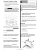
High Al tude Installa ons ATTENTION The following procedure for high al tude installa ons above 2,000 feet must be performed by a licensed professional. Failure to perform this adjustment may result in the unit shu ng down. 1. Turn off gas and power supply to unit. FIGURE 1 2. Remove 7 screws securing front panel. (FIGURE 1) 3. Remove front panel. 4. Turn on power to the unit. 5. Locate the test switch at the top of the PC Board. (FIGURE 2) 6. Press and hold the Test Switch for 1‐2 seconds.
High Al tude Installa ons 13. Adjust the Low fire se ng by using the “UP”(▲to increase) and the “DOWN” (▼to decrease) bu ons to adjust the manifold pressures per the table below. Low pressure 2,001‐5,200 Natural Gas Propane Gas FC510 0.75” W.C. 1.31” W.C. FC824 0.61” W.C. 1.17” W.C. FIGURE 3 14. Press the Test switch (FIGURE 2) again to place the unit in High fire mode. “PH” will appear on the display. 15.
Final Checklist □ □ □ □ □ □ □ □ □ □ □ □ The heater is not subject to corrosive compounds in the air. Clearances from the heater are met. The unit is not installed above 5,200 . The unit has been properly calibrated for the appropriate al tude. A manual gas control valve has been placed in the gas line to the heater. Check the gas lines and connec ons for leaks. Confirm that the gas inlet pressure is within limits. Confirm that the heater is rated for the gas type supplied.
SpecificaƟons FC510 Natural Gas Eleva on Input (BTU/h) Manifold Pressure (inch H2O) FC824 0~2000 Hi Lo Hi Lo Eleva on Input (BTU/h) Manifold Pressure (inch H2O) 10000 5500 1.8 0.64 2001~5200 9200 5500 1.8 0.75 Natural Gas 0~2000 Hi Lo Hi Lo 2001~5200 24000 8400 3.4 0.52 22000 8400 3.4 0.61 Propane Gas 0~2000 2001~5200 10000 5600 3.2 1.12 9200 5600 3.2 1.31 Propane Gas 0~2000 2001~5200 22000 8000 6.3 1.00 20000 8000 6.3 1.
Gas Fan Convec on Heater Opera on Instruc ons FC510 .................... (RCE‐391A‐H) FC824 .................... (RCE‐691TA‐H) Important Facts about your Gas Fan Convec on Heater Thank you for purchasing a Rinnai Gas Fan Convec on Heater. For proper opera on and safety, it is important to follow the instruc ons exactly and adhere to all safety precau ons. Read all of the instruc ons and the warranty thoroughly before opera ng this heater. Keep this manual in a safe place.
Consumer Opera on Guidelines for the Safe Opera on of your Fan Convec on Heater FOR YOUR SAFETY READ BEFORE OPERATING WARNING If you do not follow these instruc ons exactly, a fire or explosion may result causing property damage, personal injury or loss of life. A. This appliance does not have a pilot. It is equipped with an igni on device that automa cally lights the burner. Do not try to light the burner by hand. B. BEFORE OPERATING smell all around the appliance area for gas.
WARNING Before opera ng, smell all around the appliance area for gas. Be sure to smell next to the floor because some gas is heavier than air and will se le on the floor. Keep the area around the heater clear and free from combus ble materials, gasoline, and other flammable vapors and liquids. Due to the high surface temperature, keep children, clothing and furniture away. Keep burner and control compartment clean. Do not use this appliance if any part has been under water.
Fan Convector Manual Auto Off Button Selects thermostat off function. Auto Off Indicator Indicates the thermostat off function is activated. Economy Indicator Indicates the Economy mode is in operation. Economy Button Selects operating mode for Economy function. Off and On Timer Buttons Selects the Timer mode. (OFF or ON) Filter Indicator Indicates the filter needs cleaning. ON/OFF Button Main Switch for turning ON/OFF.
Fan Convector Manual Economy Button Selects operating mode for Economy function. Off and On Timer Buttons Selects the Timer mode. (OFF or ON) Override Button While in timer mode, changes operation from ON to OFF or OFF to ON, until the next programed setting is reached. Override Indicator Indicates Override function is activated. Off and On Timer Indicators Indicates timer is in operation.
Opera ng The Heater TURNING ON: Press the ON/OFF bu on to operate the heater. The ON indicator will glow green. A er approximately 3 seconds the spark generator will be heard before the burner ignites and the ON indicator glows red, indica ng that the burner is lit. Warm air can be felt coming from the louvers approximately 5 seconds later. Room Temperature Adjustment: NOTE The room temperature and pre‐set temperatures can only be displayed and adjusted when the heater is running.
Economy Mode: Func on Lock: Press the Economy bu on to start the Economy func on. The Economy indicator will glow. NOTE The Func on Lock will help prevent accidental opera on as well as making the control panel child resistant. To operate the Func on Lock simply press the " " and " " bu ons at the same me. The func on is ac vated immediately and the Func on Lock indica‐ tor will glow. Press the Economy bu on once more to switch off the func on.
Opera ng the Timer(s) (FC510): The Timer feature allows you to delay the start me of the heater for up to 24 hours. Opera ng the On Timer Press the On Timer bu on . The On Time indicator will illuminate and the Combus on indicator will be illumi‐ nated green to confirm that the heater is awai ng for the Delay “ON” me period to pass before commenc‐ ing opera on.
Se ng the Clock: (FC824) Programming the On/Off Timer(s) (FC824) When the appliance is first plugged in and then turned on, the digital display will show “‐ ‐:‐ ‐” A er 10 seconds the Digital Display will turn off. Example: se ng Timer 1 to heat between 7:10 A.M to 9:00 A.M. Example: se ng the clock to 10:35 A.M. 1. Press the Set Time Bu on twice. The digital display will show AM 6:00. Timer 1 Indicator will glow. 1. Press the Set Time Bu on once, the Clock Indicator will glow. 2.
Opera ng the Timer(s) (FC824): NOTE Before opera ng the Timer(s), the clock me must be correct, and a star ng me and finishing me for the Timer(s) must be programmed. The two Timers operate in the same way. This heater will begin opera ng before the programmed star ng me in order for the room to reach the temperature se ng by the programmed star ng me. 1. To select the Timer(s) to commence hea ng: Check that the me shown on the Digital Display is correct. Check the ON and OFF mes for both Timers.
Required Maintenance The appliance must be inspected annually by a licensed professional. Repairs and maintenance should be performed by a licensed professional. The licensed professional must verify proper opera on a er servicing. WARNING To protect yourself from harm, before performing maintenance: Turn off the electrical power supply by unplugging the power cord or by turning off the electricity at the circuit breaker. (The temperature controller does not control the electrical power.
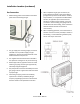
Required Maintenance (con nued) FC510 Clean as follows: Front Panel Removal FC824 1. Turn heater off. Unplug electrical cord and allow to cool for 1 hour. 2. Remove the louver assembly. (FC510: 3 Screws, FC824: 2 screws) 1. 3. Remove front panel: ‐FC510: Remove 2 screws near top and 2 screws near bo om of unit and pull front panel off towards you. (Figure 1) ‐FC824: Remove 2 screws near to top of the appliance as well as the 3 screws on the back of the control panel (Figure 3).
Required Maintenance (con nued) Removing the Filters: 1. Unscrew the cap (Philips screw in the center) securing the large filter. 2. Pull the large filter up and away. 3. For the small filter simply pull the two tabs away from the unit. WARNING Failure to keep the primary air openings of the burner clean may result in soo ng and property damage. DO NOT damage or distort any parts of the heater. DO NOT use a wet cloth or spray cleaners on the burner.
Troubleshoo ng: 1. Confirm that the heater is properly installed. See Installa on sec on. 2. Make sure the gas valve on the propane gas bo le or gas supply line is ON and that gas pressure is available. 3. Make a careful visual inspec on of all electrical connec on and wiring. 4. If trouble persists, refer to the following trouble shoo ng chart and corresponding remedy.
Diagnos c Codes This heater has the ability to check its own opera on con nuously. If a fault occurs, an Error Message will flash on the digital display of the control panel. This assists with diagnosing the fault, and may enable you to overcome a problem without a service call. Please quote the code displayed when inquiring about service. CODE DISPLAYED DEFINITION REMEDY Tilt Switch Ac vated Inspector gas line connec on, a er se ng heater upright.
Fan Convector Manual If any of the original wire as supplied with the appliance must be replaced, it must be replaced with a wire of at least a 194°F temperature ra ng and 18 AWG. Label all wire prior to disconnec on when servicing controls. Wiring errors can cause improper and dangerous opera on. Verify proper opera on a er servicing.
Fan Convector Manual If any of the original wire as supplied with the appliance must be replaced, it must be replaced with a wire of at least a 194°F temperature ra ng and 18 AWG. Label all wire prior to disconnec on when servicing controls. Wiring errors can cause improper and dangerous opera on. Verify proper opera on a er servicing.
Parts Breakdown FC510 30 Fan Convector Manual
Parts Breakdown FC510 Fan Convector Manual 31
Parts Breakdown FC510 32 Fan Convector Manual
Parts Breakdown FC510 Fan Convector Manual 33
Parts Breakdown FC510 34 Fan Convector Manual
Parts List for FC510 NO 001 003 005 007 008 010 016 018 020 021 023 025 026 100 101 102 103 104 105 106 106 107 107 108 109 112 115 116 117 118 119 120 121 121 122 123 124 125 126 129 130 131 132 133 134 PART NAME FRONT PANEL LOUVER ASSEMBLY REAR PANEL THERMOCOUPLE TEST PORT TOP PLATE ASSEMBLY INDICATER PANEL BASE HANDLE CORD HOLDER AIR FILTER‐A AIR FILTER‐B RESIN SCREW THERMISTOR COVER SECONDARY AIR COVER ASSEMBLY BURNER ASSEMBLY GAS CONTROL ASSEMBLY O RING CONNECTION PIPE CONNECTION PIPE BRACKET INJECTOR
Parts List for FC510 (con nued) NO 135 136 137 138 139 140 141 142 143 144 148 157 159 162 163 700 702 703 704 705 709 710 713 715 716 717 719 802 888 901 902 903 904 36 PART NAME BURNER LID THERMOCOUPLE BRACKET‐A THERMOCOUPLE FIXER THERMOCOUPLE BRACKET‐B CASING ASSEMBLY CONVECTION FAN BEARING BRACKET BEARING MOTOR BRACKET‐A MOTOR BRACKET‐B IGNITER BRACKET LOUVER ASSEMBLY BRACKET THROAT COVER EDGE HOLDER GUARD PLATE P.C.B.
Parts Breakdown FC824 Fan Convector Manual 37
Parts Breakdown FC824 38 Fan Convector Manual
Parts Breakdown FC824 Fan Convector Manual 39
Parts Breakdown FC824 40 Fan Convector Manual
Parts Breakdown FC824 Fan Convector Manual 41
Parts List for FC824 NO 001 003 005 007 008 010 016 018 020 021 023 025 026 100 101 102 103 104 105 106 106 107 107 108 109 112 115 116 117 118 119 120 121 121 122 123 124 125 126 128 129 42 PART NAME FRONT PANEL LOUVER ASSEMBLY REAR PANEL THERMOCOUPLE TEST PORT TOP PLATE ASSEMBLY INDICATER PANEL BASE HANDLE CORD HOLDER AIR FILTER‐A AIR FILTER‐B RESIN SCREW THERMISTOR COVER SECONDARY AIR COVER ASSEMBLY BURNER ASSEMBLY GAS CONTROL ASSEMBLY O RING CONNECTION PIPE CONNECTION PIPE BRACKET INJECTOR (Natural Ga
Parts List for FC824 (con nued) NO 130 131 132 133 134 135 136 137 138 139 140 141 142 143 144 148 159 162 700 702 703 704 705 709 710 713 715 716 717 719 802 888 901 902 903 904 PART NAME CABLE CLIP LID HEAT SHIELD SEPARATION BOARD PARTITION BOARD BURNER LID THERMOCOUPLE BRACKET‐A THERMOCOUPLE FIXER THERMOCOUPLE BRACKET‐B CASING ASSEMBLY CONVECTION FAN BEARING BRACKET BEARING MOTOR BRACKET‐A MOTOR BRACKET‐A IGNITER BRACKET GUARD PLATE EDGE HOLDER P.C.B.
State Regula ons State of Massachuse s: The installa on must be made by a licensed plumber or gas fi er in the Commonwealth of Massachuse s. Sellers of unvented propane or natural gas‐fired supplemental room heaters are to provide to the purchaser a copy of 527 CMR 30 at the me of sale of the unit. In the State of Massachuse s, unvented propane and natural gas‐fired space heaters are prohibited in bedrooms and bathrooms.
Consumer Support Warranty Informa on The installer is responsible for your heater’s correct installa on. Please complete the informa on below to keep for your records: Purchased from: _________________________________________________________________ Address: _____________________________ Phone: _________________________________ _____________________________ Date of Purchase: __________________________________ Model No.: ________________________________________ Serial No.
Limited Warranty ‐ con nued Replacement of the product may be authorized by Rinnai only. Rinnai does not authorize any person or company to assume for it any obliga on or liability in connec on with the replacement of the product. If Rinnai determines that repair of a product is not possible, Rinnai will replace the product with a comparable product at Rinnai’s discre on.
NOTES
Learn more about Rinnai high-performance Tankless Water Heaters, Hybrid Water Heating Systems, Boilers, Vent-Free Fan Convectors and EnergySaver® Direct Vent Wall Furnaces at: rinnai.us | rinnai.ca Rinnai America Corporation • 103 International Drive, Peachtree City, GA 30269 1-800-621-9419 • rinnai.us ©2017 Rinnai America Corporation. Rinnai America Corporation continually updates materials, and as such, content is subject to change without notice.