INBUILT ROYALE - ETR FLAME FIRE Customer Operation & Installation Manual This appliance shall be installed in accordance with: • Manufacturers Installation Instructions • Local Gas Fitting Regulations • Municipal Building Codes • Installation code AS/NZS 5601 ‘Gas Installations’ • Any other local relevant Statutory Regulation Installation & Service must be performed by an authorised person. This heater is NOT designed to be built directly into a combustible opening.
WARNING IMPROPER INSTALLATION, ADJUSTMENT, ALTERATION, SERVICE OR MAINTAINENANCE CAN CAUSE PROPERTY DAMAGE, PERSONAL INJURY OR LOSS OF LIFE. INSTALLATION AND SERVICE MUST BE PERFORMED BY AN AUTHORISED PERSON. This manual applies to the IB35 ETR only: Inbuilt Royale ETR - NG/LPG Table of Contents CUSTOMER INFORMATION - CONTROL PANEL .................................................. 1 CUSTOMER INFORMATION - SETTING THE CLOCK ........................................... 4 OPERATING THE TIMERS ................
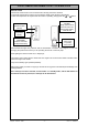
CUSTOMER INFORMATION - CONTROL PANEL TIME/TEMP Display Shows either the time of day, temperatures or coded error messages. LOCK Button Indicates lock function CLOCK ADJUSTMENT AND TIMER INDICATORS Indicates that clock or dual timer programme is being set. Flame Function Med /High heat setting and overides thermostat TIMER Indicator Indicates that TIMER 1 or TIMER 2 has been selected to operate. TIME / TEMP Adjustment Increases or decreases the temperature setting as well as changing hours or minutes.
Issue 4 CUSTOMER INFORMATION - OPERATION IMPORTANT: You must read understand these instructions before operating the heater. and fully the controls. To operate the lock simply press the LOCK button. The function is activated immediately and the LOCK indicator will glow. • To Open the Control Panel Lift lightly in the centre of the lid. The control panel lid will then open backward to an angle. To Deactivate the LOCK simply press the LOCK button for 3 seconds and the LOCK indicator will go out.
CUSTOMER INFORMATION - OPERATION Remote Control The Remote Control will not turn the heater ON if Timer(s) have been selected. To manually operate when Timer(s) are not selected, simply press the ON or OFF button. To alter the temperature at anytime while the heater is operating, simply press the or button. TO REPLACE BATTERY Simply open the back of the remote control and replace Lithium battery. TYPE: CR 2032 ON BUTTON Operates the heater manually. OFF BUTTON Stops heater manually.
CUSTOMER INFORMATION - SETTING THE CLOCK Setting the Clock When the appliance is first plugged in or after a power failure, the digital display with show --:-- As an example, let’s set the clock to 10:35 am; Press the SET TIMES button once, the Clock indicator will flash. Press and hold the “” button; the minutes will begin to change first then the time will change by whole hours. Release the button when AM 10:00 shows on the Digital Display.
Issue 4 OPERATING THE TIMERS Operating the Timers Before operating the Timer(s), the clock time must be correct and a starting time and finishing time for the Timer(s) must be programmed. See page 5. The two Timers operate in the same way. This heater does not commence operation at the programmed starting time. It will attempt to heat a room by the programmed starting time. See Pre-heat, for further explanation. To select the Timer(s) to commence heating.
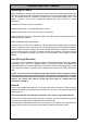
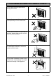
CUSTOMER INFORMATION - SAFETY POINTS Clearances must be maintained. min. 300mm min. 300mm min. 300mm min. 1000mm Note that side and vertical clearances are measured from the edge of the glass. Do not restrict the warm air discharge by placing articles in front of the heater. Do not spray aerosols whilst the heater is operating. Most aerosols contain butane gas, which can be a fire hazard if used near the heater when it is in use. This appliance must not be used for any purpose other than heating.
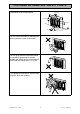
CUSTOMER INFORMATION - SAFETY POINTS Issue 4 Do not allow anyone to post articles through the louvres. Do not allow young children or the infirm to sleep directly in front of the heater. Young children should be supervised at all times. Hand or body contact with the louvres must be avoided. Do not allow curtains or other flammable or combustible materials to come into contact with the heater. Do not place containers of liquid on top of the heater.
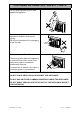
CUSTOMER INFORMATION - SAFETY POINTS Do not allow anyone to sit on or lean against the appliance. Do not unplug the heater while it is in operation or while the fans are still cycling. Do not turn the heater off by unplugging it from the wall. Do not remove the Dress Guard. The dress guard is fitted to this appliance to reduce the risk of fire or injury from burns and no part of it should be permanently removed. For protection of children or the infirm, a secondary guard is recommended.
CUSTOMER INFORMATION - ERROR CODES ERROR CODE MESSAGE E The Flame Fire ETR has the ability to check its own operation continuously. If a fault occurs, an Error Message will flash on the Digital Display of the control panel. This assists with diagnosing the fault, and may enable you to overcome a problem without a service call. Please quote the code displayed when enquiring about service. Error Code --:-- Probable Cause Comments • Ignition Failure • Check gas is turned on.
CUSTOMER INFORMATION - TROUBLE SHOOTING SYMPTOM Burner will not light POSSIBLE CAUSES SOLUTION • No power present • Ensure power cord is plugged in and turned on. • No gas present • Ensure gas supply is turned on. • Power cut • Re-ignite when power is restored. • Air in gas supply pipe • Purge air (installer). • Ignition failure • Repeat lighting procedure (refer operating instructions page 2). Smell of gas • Leaking gas • Turn off gas at meter and call installer.
Issue 4 Intentionally Blank Inbuilt Royale - ETR - 11 - Issue 4 - ©Rinnai
CUSTOMER INFORMATION - IMPORTANT POINTS Issue 4 Unpack the heater and check for damage. DO NOT INSTALL DAMAGED HEATER. If the heater is damaged, contact your supplier for advice. Before installing the heater, check the label for the correct gas type (see rating plate, front right hand side of bottom panel). Refer to local gas authority for confirmation of the gas type if you are in doubt. Included in the carton Customer operation information, roll of sealing foam, ceramic log set and granules.
CUSTOMER INFORMATION - SPECIFICATIONS Model: IB35ETRN (NG) IB35ETRL (Propane) Description: Rinnai Inbuilt Radiant/Convector, glass fronted, ceramic log space heater with forced convection & natural draft flue system. Output: 33 MJ/hr Natural Gas and Propane. Gas Control: Rinnai Electronic Control Valve Burners: Ceramic Logs, Ember bed and Heat burner Gas Inlet: 15 mm. Copper Flare Connection. Test Point Pressure: Natural Gas 0.95 kPa; Propane: 2.00 kPa.
Issue 4 INSTALLERS INFORMATION - LOCATION The following pages contain information relating to Installation and Service. Installation and Service must be carried out by an authorised person only. 8. Before installing the heater, inspect the chimney, flue piping and/or solid fuel burning fire place and remove any combustible materials. When positioning the heater, the main points governing the location are: 9.
TECHNICAL SPECIFICATION Model: Description: Gas input rate: Gas Control: Burners Test Point Pressure: Gas Connection: Flue terminal: Fan: Combustion system Logs: Ignition system: Operation: Safety Devices: Combustion method: Installation type: Weight: Flue requirement: Inbuilt Royale - ETR Flame Fire IB35ETR Rinnai ETR Inbuilt Radiant/Convector, glass fronted, ceramic log space heater with forced convection and natural draught flue system Natural Gas Propane Pilot and ‘Low’: Medium: High: Rinnai electr
INSTALLERS INFORMATION - DIMENSIONS 17 319 400 585 167 150 17 400 Inbuilt Royale - ETR - 16 - 583 575 695 ~ 700 8 910 Issue 4- ©Rinnai
INSTALLATION INTO MASONRY FIREPLACE & CHIMNEY A Rinnai Flexible Flue Liner Kit (Flexliner01) is mandatory in all masonry fireplace and chimney installations. MASONRY FIREPLACE HEATER 1. Check Dimensions of Fireplace Check dimensions of fireplace and if necessary bring them to the dimensions shown. • If the fireplace opening is larger than the heater, a 100mm wide decorative surround Part no.
INSTALLATION INTO MASONRY FIREPLACE & CHIMNEY 4. Apply sealing strips to back of heater • Peel protective backing off the foam strips supplied with the Heater. • Attach strips to rear of casing as shown. The strip is intended to form a seal between the heater and the fireplace. • If an adequate seal cannot be formed with this strip an other means of sealing must be used. (eg.non combustible insulation), between the fireplace and the heater body. SEALING STRIPS 5.
INSTALLATION INTO MASONRY FIREPLACE & CHIMNEY 10.Slide out the fan partition tray exposing the gas control and flare connection. 11. Slide the heater carefully into position, while feeding the stainless steel flexi-tube through the gas supply access opening at right hand rear. 12.Bend the flexi-tube and connect to the gas control valve. Note: All foreign materials such as filings and swarf must be purged from the gas supply before connection as they may damage the gas controls. 13.
INSTALLATION IN TO A COMBUSTIBLE OPENING Rinnai understands that not all households have an existing masonry fireplace. Rinnai offers the option of installing the Flame Fire Royale into a decorative fireplace for either a single storey or two storey home. All you need is a flat wall which can be either external or internal and a zero clearance box. A Rinnai Rigid flue MUST also be installed (Part No. FLFKIT05 / FLFTWKIT). Flexible flue kits are not suitable.
INSTALLATION IN TO A COMBUSTIBLE OPENING Steps for Installation: 1. Determine the preferred location of the heater. • Check roof space for any flue obstructions. 2. Construct frame in accordance with the dimensions shown: 745 mm 440 mm 810 mm 3. Install Rinnai Zero Clearance Box (ZEROR) • ‘Zero clearance’ means the panels of metal from the zero clearance box can be in contact with any combustible material. • The hearth surface must be flat and level to support the zero clearance box.
INSTALLATION IN TO A COMBUSTIBLE OPENING 4. Run gas supply. For pipe sizing refer to your local gas installation codes. Copper supply should be run leaving a flared connection at the position shown. Attach the stainless steel flexitube supplied to the flared connection. 5. Install Rinnai Flame Fire Rigid Flueing as per the instructions supplied with the flue kit, taking careful note of the following: Flue termination above the roof must comply with AS/NZS 5601. Vertical flue length must be no less than 3.
INSTALLATION IN TO A COMBUSTIBLE OPENING 10.Install top decorative surround to face of fireplace. 11. Log Installation - for log installation details, please refer to page 24. 12.Commissioning - for Commissioning details, please refer to page 27.
INSTALLERS INFORMATION - LOG INSTALLATION 1. The log set is packed inside the heater and the packaging must be removed prior to installing the log set in its correct position • • • • • • Open both side panels. Remove fastenings on both sides of the top glass retainer. Lift retainer away from heater. Loosen screws on bottom glass retainer. Carefully lift glass out of bottom channel. Carefully remove log packaging.
INSTALLERS INFORMATION - TESTING & COMMISSIONING 1. To check burner pressure • Turn OFF and disconnect the 240V power supply connection. • Turn ON Gas supply. • Refer to Data Plate or the Technical Specification section in this manual for burner pressures. • If you are unable to get the unit to operate correctly, refer to Trouble Shooting on page 10 before contacting your local service contacts listed on the back page of this booklet.
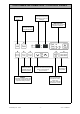
INSTALLERS INFORMATION - WIRING DIAGRAM WIRING DIAGRAM ETR WITH DELAY CIRCUIT AC 220V/240V XLP-02V(JST) 1 CN1 2 XLP-03V(JST) 1 2 CN3 3 (BR) (BL) YLP-03V(JST) YLR-03V 1 2 3 1 2 3 * TRANSFORMER SPARKER (GY) (GY) 4 5 6 6 5 4 3 2 1 (REAR) SV2 (BW) (RW) (R) (W) (BK) (BK) (BL) (BL) (R) CONTROL RECEIVER LO HI XLP-04V 2 4 1 3 C XMP-03V 3 2 CN8 1 917687-1 3 2 CN11 1 (BK) 917690-1 (R) 917694-1 1 FLUE BLOCK THERMISTER (W) OVER HEAT THERMISTER (BK) ROOM TEMP THERMISTER 10KR-8M (FRONT) (BK)
INSTALLATION / COMMISSIONING CHECKLIST (To be completed by certified Gas Installer) NO YES Model: _______________________________ 1. Was a fireplace inspection carried out? (i.e. clearances, combustibles etc). 2. Was a Rinnai flue system installed in accordance with the instructions? 3. Have specified gas pressures been checked and set? 4. Are decorative logs located correctly? 5. Have ember granules been placed and free of dust and powder? 6.
NOTES Inbuilt Royale - ETR - 28 - Issue 4- ©Rinnai
CUSTOMER INFORMATION - CONTACTS The Rinnai Flame Fire Heater Family Inbuilt Royale IB35 / IB35ETR Australia Pty. Ltd. Head Office Freestanding Royale FS35 / FS35ETR Inbuilt Slimfire IB25 ABN 74 005 138 769 Internet: www.rinnai.com.au E-mail: enquiry@rinnai.com.au 10-11 Walker Street, Braeside, Victoria 3195 P.O.