INSTALLATION AND OPERATION MANUAL I-Series Condensing Boiler Wall-Mounted, Gas-Fired Solo Boiler Central Heating Boiler SOLO MODELS i060S i090S i120S i150S (REB-A1800FF-US) (REB-A2600FF-US) (REB-A3500FF-US) (REB-A4400FF-US) Certified to ANSI Z21.13 and CSA 4.9 If the information in these instructions are not followed exactly, a fire or explosion may result causing property damage, personal injury, or loss of life.
1. Welcome ................................................................................................................................................... 4 2. Safety ........................................................................................................................................................ 5 2.1 Safety Symbols ..................................................................................................................................................... 5 2.
8.4 Simultaneous CH and DHW Operation .............................................................................................................. 64 8.5 Indirect Tank Parameter Settings ....................................................................................................................... 65 8.6 Piping Diagram for a Basic DHW Installation ..................................................................................................... 66 9. Power Supply ...............................
1 Thank you for purchasing a Rinnai Condensing Boiler. Before installing and operating this boiler, be sure to read these instructions completely and carefully to familiarize yourself with the boiler’s features and functionality. • You must read the entire manual to • • properly operate the boiler. • Keep this manual for future reference. • As when using any appliance generating heat, there are certain safety precautions you should follow. See section “2.
2 WARNING • • • • • If the information in these instructions is not followed exactly, a fire or explosion may result causing property damage, personal injury, or death. Do not store or use gasoline or other flammable vapors and liquids in the vicinity of this or any other appliance. WHAT TO DO IF YOU SMELL GAS: − Do not try to light any appliance. − Do not touch any electrical switch; do not use any phone in your building. − Immediately call your gas supplier from a neighbor’s phone.
• Do not use this appliance if any part has • • • • • • • 6 been under water. Immediately call a licensed professional to inspect the appliance and replace any part of the control system and any manual gas control valve which has been under water. Do not use substitute materials. Use only parts certified for the appliance. Should overheating occur or the gas supply fail to shut off, turn off the manual gas control valve to the appliance.
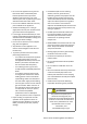
3 Topics in this section • • • • • • Front View Bottom View Components Specifications Dimensions Accessories The I-Series Condensing Boiler is a wall-mounted, gas-fired boiler designed to provide heating to the building with the ability to connect an indirect tank for DHW production. For complete boiler information, refer to the “Rinnai I-Series Condensing Boiler Installation Manual” supplied with the boiler, or visit rinnai.us.
Gas Central Heating Supply Central Heating Return All items are field-supplied unless otherwise noted.
Intake Exhaust Flue Gas Exhaust Air Intake Air Inlet Filter Fan with Integrated Venturi Air Vent Burner Assembly Gas Valve Ignition Unit Heat Exchanger Silencer PC Board Cover Control Panel Pressure Sensor PC Board Removed Condensate Trap Rinnai I-Series Condensing Boiler Solo Manual 9
Model i060S Dimensions - w, h, d i090S i120S 18.5 in. x 26.4 in. x 10.9 in. (471 mm x 671mm x 276 mm) Weight 59.2 lb (27 kg) 62.
Measurements: in. (mm) Vent Connection: 2 in. (51 mm) nominal PVC/Polypropylene or 3 in./5 in.
Central Heating Return Central Heating Supply Gas Condensate Drain Connection 12 Connection Size Gas 3/4 in. NPT CH In (CH Return) 1 in. NPT CH Out (CH Supply) 1 in. NPT Condensate Outlet 1/2 in.
The following optional accessories are available for the Rinnai I-Series Condensing Boiler. CONDENSATE NEUTRALIZER Neutralizes the condensate generated by the boiler. SCALECUTTER REFILL CARTRIDGE SCALECUTTER Filters and reduces the amount of scale entering the boiler allowing for greater boiler longevity. PRIMARY-SECONDARY HEATING KIT Refill cartridge for the ScaleCutter filter assembly.
4 Topics in this section • • • • • • Installation Guidelines What You’ll Need Items Included Choose an Installation Location Mount the Boiler to the Wall Fill the Condensate Collector THIS SECTION IS INTENDED FOR THE INSTALLER Installer qualifications: A trained and qualified professional must install the appliance, inspect it, and leak test the boiler before use. The warranty will be voided due to any improper installation.
• Ensure the wall is of sufficient strength to support the weight of the boiler, piping and any other components needed for installation; if it is not, please reinforce the wall as appropriate. • Operating limits of the boiler: Maximum boiler set point temperature: 180°F (82 °C) Gather the recommended tools and parts before starting installation. Items Needed • • Maximum operating 45 psi (3.1 bar) pressure: Maximum allowable 210°F (99°C) working temperature ASME: Maximum allowable 45 psi (3.
Carefully unpack your boiler system and verify the following contents are included. If any items are damaged or missing, contact your local dealer/distributor. Do not attempt to use any item that appears damaged. RINNAI CONDENSING BOILER Vent top with integrated 2 in. PVC and 3 in. X 5 in. Concentric Vent Adapter Integrated Items Air Supply Filter Refer to section “3.3 Components” for a complete list of integrated parts.
When choosing an installation location, you must ensure that clearances will be met and that the vent length will be within required limits. Consider the installation environment, water quality, and need for freeze protection. Requirements for the gas line, water lines, electrical connection, and condensate disposal can be found in their respective installation sections in this manual. This section provides information on the importance of water quality to the Rinnai Condensing Boiler.
Air surrounding the boiler, venting, and vent termination(s) is used for combustion and must be free of any compounds that cause corrosion of internal components. These include corrosive compounds that are found in aerosol sprays, detergents, bleaches, cleaning solvents, oil based paints/varnishes, and refrigerants. The air in beauty shops, dry cleaning stores, photo processing labs, and storage areas for pool supplies often contains these compounds.
Insert the top bracket into the wall mounting bracket. Make sure the wall mounting bracket is attached to the wall and can hold the weight of the boiler before you fully let go. You Will Need: • • Rinnai Condensing Boiler Wall Mounting Bracket Supplied by Installer: • • • Level Four screws for mounting bracket installation Screws for top and bottom bracket installation Use appropriate screws for type of wall construction.
Securely screw the top and bottom brackets into the wall, making sure the screws are flush with the wall. • Use any of the holes in the top and bottom brackets. • Make sure the securing method is sufficient to support the weight of the boiler. Refer to the boiler weight in section “3.4 Specifications” of this manual. IMPORTANT The boiler must be installed in an upright and level position. Do not install the boiler upside down or on its side.
5 Topics in this section • • • • • Guidelines Venting Installation Sequence Termination Considerations PVC Venting Safety Switch Venting Options • I-Series boilers can be installed in direct vent or non-direct vent applications. • When installed as Direct Vent, refer to the following section for a complete list of approved vent manufacturers and products: “5.5.1 Direct Vent: Approved Vent Manufacturers and Products.” • Venting should be as direct as possible with a minimum number of pipe fittings.
The vent for this appliance shall not terminate: • Over public walkways. • Near soffit vents or crawl space vents 1. Determine the termination method—horizontal or vertical, concentric, or twin pipes, etc. 2. Determine proper location for wall or roof penetration for each termination. 3. Install termination assembly as described in this manual or in the vent manufacturer’s installation instructions. 4. Install air and vent piping from boiler to termination. 5.
The instructions in this section explain how to adjust boiler settings to allow for higher exhaust temperatures. These instructions apply only for installations using CPVC, listed Polypropylene, or stainless steel venting. If these instructions are not followed exactly, a fire or carbon monoxide leak may result causing property damage, personal injury, or death. WARNING DO NOT adjust boiler settings to allow higher exhaust temperatures when venting with PVC.
5. Press the Mode button on the controller. 01-A 6. Press the (Up) or Select button. (Down) arrows until A2-A appears in the display. Then, press the A2-A Select button 7. Press the (Up) or (Down) arrows until A2- appears in the display. Then, press the Select button. A2Select button 8. The boiler is now set to allow higher exhaust temperatures. To exit parameter settings and enter normal operation mode, press the Mode button. 9.
Two venting options are available: Direct Vent and Non-Direct Vent (Room Air). Option 1 Direct Vent (Concentric and Twin Pipe) See the Direct Vent section for complete details. Concentric Pipe Combustion air and exhaust vent directly through a single concentric connection. Hot exhaust exits through the interior pipe, while combustion air enters through the outer pipe. Twin Pipe Combustion air and exhaust vent directly through separate penetrations.
Following is a list of vent components and terminations for Direct Vent installations (concentric and twin pipe). Install the correct venting for your model according to the venting manufacturer’s instructions and the guidelines below. The information below is correct at time of publication and is subject to change without notice. Contact the vent manufacturer for questions related to the vent system, products, part numbers and instructions. Manufacturer Phone Web Site Ubbink 800-621-9419 www.rinnai.
Equivalent Length (ft) Vertical Horizontal Diagram Product Description Manufacturer Part Number Manufacturer 2 in./4 in. CONCENTRIC VENT TERMINATIONS (Continued) CENTROTHERM ROYAL 52CVKGVS6502 PVC Concentric Vent Kit 2 in. x 16 in. 20 52CVKGVS6502-28 PVC Concentric Vent Kit 2 in. x 28 in. 20 52CVKGVS6502-40 PVC Concentric Vent Kit 2 in. x 40 in. 20 ICRT2439 20 DURAVENT 2PPS-VKL/VK-TCL ECCO 2 in. x 4 in. Concentric Roof Termination 2 in. x 4 in.
Equivalent Length (ft) Vertical Horizontal Diagram Product Description Manufacturer Manufacturer Part Number 3 in./5 in. CONCENTRIC VENT TERMINATIONS UBBINK 3 in./5 in. CONCENTRIC VENT TERMINATIONS 223174PP 3/5 Condensing Horizontal Termination Kit 8.7 in. 223176PP 3/5 Condensing Horizontal Termination Kit 12 in. 223177PP 3/5 Condensing Horizontal Termination Kit 21 in. 223186PP 3/5 Condensing Horizontal Diverter Termination Kit 19 in.
Equivalent Length (ft) Vertical Horizontal Diagram Product Description Manufacturer Part Number Manufacturer 3CGRLSV Vertical Adapter 3CGRLSH Horizontal Adapter 3CGRVT Vertical Termination 3CGRHT Horizontal Termination 3PPS-VKL/VK-TCL 3 in. x 5 in. Vertical Termination Cap KitConcentric 3PPS-HKL 190388 ECCO 1 6 5 DURAVENT METAL-FAB 3 in./5 in. CONCENTRIC VENT TERMINATIONS (Continued) 190395 16 20 3 in. x 5 in. Horizontal Termination Kit-Concentric 20 3 in. x 5 in.
Equivalent Length (ft) Vertical Horizontal Diagram Product Description Manufacturer Part Number Manufacturer 2 in. TWIN PIPE TERMINATIONS IPEX DURAVENT CENTROTHERM 2 in. TWIN PIPE TERMINATIONS ISELL0287UV 2 in. 87° Long PPS-UV ISTT0220 2 in. Termination Tee ISLPT0202 2 in. Low Profile Wall Termination 2PPS-HTPL 2 in. Twin Pipe Termination 2PPS-HSTL 2 in. Single Horizontal Termination 2PPS-TBL 2 in.
Equivalent Length (ft) Vertical Horizontal Diagram Product Description Manufacturer Part Number Manufacturer 3 in. TWIN PIPE TERMINATIONS IPEX DURAVENT CENTROTHERM 3 in. TWIN PIPE TERMINATIONS ISELL0387UV 3 in. 87° Long PPS-UV ISTT0320 3 in. Termination Tee ISLPT0303 3 in. Low Profile Wall Termination 3PPS-HTPL 3 in. Twin Pipe Termination 3PPS-HSTL 3 in. Single Horizontal Termination 3PPS-TBL 3 in.
Air Filter Screen Equivalent Length (ft) Vertical Horizontal Diagram Product Description VARIOUS 2 in. OR 3 in. SCHEDULE 40 PVC/CPVC TERMINATIONS N/A Tee 5 90° Elbow 5 45° Elbow 2.
The information below applies to Concentric and Twin Pipe. TERMINATION Clearance in Ref. A also applies to anticipated snow line X AIR SUPPLY INLET V VENT TERMINAL AREA WHERE TERMINAL IS NOT PERMITTTED SNOW Ref A B C Description Clearance above grade, veranda, porch, deck, or balcony Clearance to window or door that may be opened Clearance to permanently closed window Canadian Installations (CSA B149.1) U.S. Installations (ANSI Z223.1 /NFPA 54) Direct Vent (Indoor Unit) 12 in. (30 cm) 36 in.
Between terminals at different levels 60 in. (1.52 m) Note: 24 in. (0.61 m) to wall or parapet 12 in. (0.30 m) 12 in. (0.30 m) 60 in. (1.52 m) vertically between terminals Inside Corner Between terminals at same level 12 in. (0.30 m) All terminations (horizontal and/or vertical) must terminate 12 in. (0.30 m) above grade or anticipated snow level. Vent Sizes: 2 in. X 4 in. 3 in. X 5 in.
The instructions below apply to concentric vent sizes 2 in. x 4 in. and 3 in. x 5 in. Remove and discard screw from concentric flue connection. Horizontal Wall Terminations 2 in. x 4 in. and 3 in. x 5 in. Remove exhaust adapter ring (discard for concentric venting configurations). Vertical Roof Terminations 2 in. x 4 in. and 3 in. x 5 in. Install the concentric vent. Ensure it is properly seated. Concentric Vent Secure the vent pipe to the concentric flue connection with the supplied screw.
Twin Pipe Vertical Termination of Multiple Boilers Horizontal Vent and Combustion Air Piping X 12 in. (0.30 m) minimum X 12 in. (0.30 m) minimum 60 in. Exhaust 12 in. (0.30 m) minimum above combustion air opening 12” Combustion Air X 12 in. (0.30 m) above grade or anticipated snow level Roof X V 8 in. 9 in. X X 60 in. Tee Sidewall 12” Exhaust 4” 36 in. minimum clearance from intake to grade, ground, or anticipated snow level.
This boiler is equipped with a 2 in. PVC pipe connection. With the use of a pipe reducer, installers can use a 3 in. pipe for the combustion air and exhaust. WARNING DO NOT apply PVC glues, solvents, or cleaners to the boiler’s combustion air or exhaust gasket connections. Failure to correctly assemble the components according to these instructions may result in property damage, personal injury, or death. Remove and discard the screw from the combustion air vent connection.
Slope horizontal exhaust 1/4 in. per foot towards the boiler. DO NOT slope combustion air pipe towards the boiler. CAUTION Rinnai cautions against installing the boiler in applications with venting in different pressure planes. It is possible to have poor performance with this installation. This configuration requires the use of a Concentric Vent Termination. This configuration requires the use of a Concentric Vent Termination. 2 in. or 3 in.
TERMINATION Clearance in Ref. A also applies to anticipated snow line X AIR SUPPLY INLET V VENT TERMINAL AREA WHERE TERMINAL IS NOT PERMITTTED SNOW Ref A Description Clearance above grade, veranda, porch, deck, or balcony Canadian Installations (CSA B149.1) Other than Direct Vent (Room Air) 12 in. (30 cm) U.S. Installations (ANSI Z223.1 /NFPA 54) Other than Direct Vent (Room Air) 12 in. (30 cm) 36 in. (91 cm) 4 ft (1.
Room Air Vertical Termination of Multiple Boilers 12 in. (0.30 m) minimum Exhaust 12 in. (0.30 m) above grade or anticipated snow level Roof Exhaust Termination Clearances for Internal (Indoor) Room Air Applications 12 in. 12 in. (0.30 m) 60 in. (1.52 m) Vertically between terminals Inside Corner IMPORTANT • • 40 Installation of Room Air must use listed Category IV venting. All terminations (horizontal and/or vertical) must terminate 12 in. above grade or anticipated snow level.
• 2 in. PVC • 2 in. (60 mm) PP Vent Sizes • 3 in. PVC • 3 in. (80 mm) PP 65 ft (20 m) Vent Lengths 150 ft (46 m) • 45° elbow is equivalent to 3 ft (1 m) • 90° elbow is equivalent to 6 ft (2 m) Vent length includes the additional venting, fittings and terminations. ACCEPTABLE ACCEPTABLE NOT ACCEPTABLE 90° Elbows, Long Sweep 90° Elbows, Short Sweep 90° Elbows, Close Turn WARNING • • This boiler requires adequate combustion air for ventilation and dilution of flue gases.
Unconfined Space An unconfined space is defined in National Fuel Gas Code, ANSI Z223.1/NFPA 54 as “a space whose volume is not less than 50 cubic feet per 1000 Btu/hr (4.8 m3 per kW per hour) of the aggregate input rating of all appliances installed in that space. Rooms communicating directly with the space in which the appliances are installed, through openings not furnished with doors, are considered a part of the unconfined space.
Location To maintain proper circulation of combustion air two permanent openings (one upper, one lower) must be positioned in confined spaces. The upper shall be within 12 in. (0.30 m) of the top of the confined space and the lower opening shall be within 12 in. (0.30 m) of the bottom of the confined space. Openings must be positioned as to never be obstructed. 12 in. (300 mm) 10 in.
Remove and discard screw from combustion air vent connection. Remove and discard the combustion air vent cap. Install the combustion air vent pipe. Ensure it is properly seated. Secure the combustion air vent pipe to the combustion air vent connection with the supplied screw. Place the vent screen or room air screen inside elbow and secure with the supplied screw. Use the room air screen for environments where room air is dusty. Notes: • 2 in. vent screen supplied with boiler.
CAUTION Rinnai cautions against installing the boiler in applications with venting in different pressure planes. It is possible to have poor performance with this installation. 2 in. or 3 in. Schedule 40 PVC/CPVC Snorkel Termination Configuration 2 in. or 3 in. Schedule 40 PVC/CPVC Standard Upside Down "U" Vertical Termination Configuration 2 in. or 3 in. Schedule 40 PVC/CPVC Elbow or Tee Side Wall Termination Configuration 2 in. or 3 in.
6 Topics in this section • • • Connect the Gas Supply Gas Operating Instructions Gas Pipe Sizing Reference Tables WARNING • A licensed professional must install the gas supply. Turn off 120V power supply. Turn off the gas. Gas is flammable. Do not smoke or provide other ignition sources while working with gas. Do not turn on the boiler or gas until all fumes are gone.
FOR YOUR SAFETY READ BEFORE OPERATING WARNING: If you do not follow these instructions EXACTLY, a fire or explosion may result causing property damage, personal injury or loss of life. A. This appliance does not have a pilot. It is equipped with an ignition device which automatically lights the burner. Do not try to light the burner by hand. B. BEFORE OPERATING smell all around the appliance area for gas. Be sure to smell next to the floor because some gas is heavier than air and will settle on the floor.
The gas supply must be capable of handling the entire gas load required at the location. Gas line sizing is based on gas type, the pressure drop in the system, the gas pressure supplied, and gas line type. For gas pipe sizing, refer to the National Fuel Gas Code, ANSI Z223.1/NFPA 54, or the Natural Gas and Propane Installation Code, CSA B149.
Natural Gas EXAMPLE Rinnai Model Gas Input: Pressure Drop 3.0 in. w.c. Intended use: Initial supply pressure of 8.0 in. w.c. or greater. Information in table obtained from NFPA 54, ANSI Z223.1 - 2015. Schedule 40 Metallic Pipe Inlet Pressure: Less than 2 psi Specific Gravity: 0.
7 Topics in this section • • • • • • • • • Guidelines Instructions Common CH Components Piping Diagram for a Basic CH System (Without Hydraulic Separation) Piping Diagram for a Basic CH System (With Hydraulic Separation) Hydraulic Separation Connect the Pressure Relief Valves Connect the Condensate Drain Line Condensate Pump Safety Switch Wiring • • • It is required to include an air separator on the central heating supply of the system.
Plumb the heating supply line to the heating supply connection on the bottom of the boiler. • Pressure Relief Valve (PRV) — A PRV located directly on the supply side of the boiler is required. The PRV must be 3/4 in. with at least 30 PSI (207 kPa) and a maximum of 45 PSI (310 kPa). A 30 PSI (207 kPa) PRV is supplied with the boiler. A port for the central heating PRV is present in the PrimarySecondary Heating Kit accessory offered by Rinnai.
CH System Common Components Diagram Low Water Cut Off (if required by local code) Pressure Relief Valve (supplied with boiler) Pressure Gauge Boiler Pump Air Separator SYSTEM SUPPLY Primary-Secondary Heating Kit Dirt Trap Ball Valve Fill valve with pressure gauge Backflow Preventer Expansion tank 52 Rinnai I-Series Condensing Boiler Solo Manual SYSTEM RETURN
Optional Low Water Cut-Off (LWCO) IMPORTANT This schematic shows an example of a simple single zone system without primary/secondary piping. Outdoor Sensor This piping arrangement is possible for a system that has one or a few small zones and a low pressure drop that can be overcome by the main boiler pump. A bypass line is recommended to allow circulation if the freeze protection function of the boiler is engaged.
Optional Low Water Cut-Off (LWCO) IMPORTANT This schematic shows an example of a simple single zone system with primary/secondary piping by hydraulic separation. Outdoor Sensor Thermostat Purge Station Heat Emitter This is not an engineering drawing; it is intended only as a guide and not as a replacement for professional engineering project drawings. This drawing is not intended to describe a complete system.
Rinnai recommends hydraulic separation between the boiler and central heating system. Hydraulic separators allow for no pump curve matching or flow calculation; this is ideal for multi-temperature and multi-zone systems. Examples of Hydraulic Separation Closely spaced tees and low loss headers are common examples of hydraulic separators and can be used to separate the boiler loop from the central heating loop.
Pressure Loss (Feet of Head) The I-Series Solo Boiler does not have an included a boiler pump. An external boiler pump must be installed and sized to the flow rate and pressure drop through the boiler, system piping, and system components. Larger systems, or systems with large pressure drops, should incorporate a form of hydraulic separation, such as closely spaced tees or a low loss header.
WARNING Water discharged from the pressure relief valve could cause severe burns instantly or death from scalds. • The discharge end of the line shall be plain (unthreaded) and a minimum of 3/4 in. nominal pipe diameter. The discharge line material must be suitable for water at least 180° Fahrenheit. • If a pressure relief valve discharges An approved pressure relief valve is required by the American National Standard (ANSI Z21.
• • Do not plumb the condensate drain with the pressure relief valve; both must be plumbed independently to drain. • All condensate must drain and be disposed of according to local codes. • Use only corrosion resistant materials for the condensate drain lines such as PVC pipe or plastic hose. • The condensate drain pipe (along its entire length) must be at least 1/2 in.
4. Select an appropriate length of wire (18 AWG or greater) and strip the insulation off the ends. Follow the wiring guidelines established by the National Electrical Code (NEC). To connect the condensate drain pipe: 1. Apply thread sealant to 1/2 in. NPT condensate drain port. 2. By hand, thread 1/2 in. NPT fitting onto condensate drain port. 3. Follow the steps in the next section: “7.9 Condensate Pump Safety Switch Wiring.
Condensate Pump Safety Switch Installation Boiler To Condensate Pump Safety Switch Wires Wire Nut Connecting Two Wires Installer-Supplied Wires Safety Switch Wires* Condensate Pump (installer-supplied) Includes internal safety switch and power cord. Power cord must be plugged into power source. * Safety switch wires connect to the NO and COM contacts on the safety switch.
8 Topics in this section • • • • • • Guidelines Indirect Tank Control Options Indirect Tank Electrical Connections Simultaneous CH and DHW Operation Indirect Tank Parameter Settings Piping Diagram for a Basic DHW Installation This boiler provides DHW through an indirect tank. The boiler incorporates temperature control features for the boiler and indirect tank controls, including indirect tank heating priority.
When DIP Switch 3 is in the OFF (default) position Parameter 32 becomes available. The option to select an indirect tank pump (default) or a 3-Way Valve with the boiler pump for recovering the indirect tank becomes available. If the 3-Way Valve option is desired, only 120VAC 3-Way Valves may be used. Do not use a 3-Way Valve if simultaneous CH and DHW via an indirect tank is desired. NOTE • Refer to section “9.2 Electrical Connections” for more information on the boiler’s electrical connections.
Indirect Tank Thermostat Connection ON DIP Switches Indirect Tank Pump Connection OFF Indirect Tank Thermostat Connection PC Board Indirect tank pump to be wired to boiler.
The boiler has the ability to operate simultaneously between central heating and domestic indirect tank heating. The boiler can control dividing the flow between domestic hot water production to the indirect tank and the central heating circuit. The boiler is set to domestic indirect tank recovery as the priority.
NOTE Refer to section “12.4.1 Parameter Settings Table” for more information on parameter settings. Parameter Number Setting Description A 180°F (82°C) Indirect Tank Supply Temperature with Thermistor Control 30 31 32 Indirect Tank Supply Temperature with Thermostat 180°F (82°C) 160°F (71°C) 140°F (60°C) Allowed Indirect Tank Temperature Drop before 5.4°F (3°C) 10.8°F (6°C) 16.2°F (9°C) Indirect Tank Operation Option Use Pump Use 3-Way Valve Indirect Tank Simultaneous Heating 33 d 21.
This is not an engineering drawing; it is intended only as a guide and not as a replacement for professional engineering project drawings. This drawing is not intended to describe a complete system. It is up to the contractor or engineer to determine the necessary components and configuration of the particular system to be installed. The drawing does not imply compliance with local building code requirements.
9 CAUTION Topics in this section • Guidelines Electrical Connections Post-Power Supply Connection Checklist • • • • • WARNING • Do not use an extension cord or adapter plug with the boiler.
Devices such as the room thermostat and outdoor temperature sensor are connected to the boiler PC Board. Item ❶ ❷ ❸ Connection Item Note ❶ Boiler Pump 120 VAC, Max 2.0 A ❷ External Pump Connection 2/ 120 VAC, Max 2.0 A Indirect Pump ❸ External Pump Connection 1 ❹ T/T 1 Connection ❺ T/T 2 Connection/Indirect Tank Thermostat Connection ❻ LWCO (High Limit or Other Safety Switch) ❼ Outdoor Temperature Sensor ❽ Indirect Tank Thermistor ❾ 24V AC for External Output 120 VAC, Max 2.
10 Topics in this section • • • Safety Precautions Filling Process Deaeration Process THIS SECTION IS INTENDED FOR THE INSTALLER This boiler must be commissioned by a licensed professional. Installer qualifications: A trained and qualified professional must install the appliance, inspect it, and leak test the boiler before use. The warranty will be voided due to any improper installation.
You Will Need: • Philips head screwdriver 1. Remove the boiler’s front panel by removing the four screws that secure the panel. Note: Alternately, on initial installation, you may press and hold the Indirect Tank button, then simultaneously press the CH button on the control panel instead of removing the boiler’s front panel. 2. On the PC Board, press and hold the top, left black button shown below. The Maintenance Required icon (see right image) on the controller display will appear.
Deaeration is an effective method of purging air from the boiler after the system has been filled or serviced. While the boiler is running the deaeration process, the Maintenance Required icon (see right image) appears on the controller display. Do not bypass deaeration during commissioning or if the system pressure has dropped below 13 PSI (90 kPa). If there is any chance that air has entered the system, deaeration is critical to prevent damage to the boiler.
11 Complete the following checklist when boiler installation is complete. You should be able to answer YES to each question. If you answer NO, installation is not complete. Refer to the applicable section in this manual for additional information.
PRESSURE RELIEF VALVE (PRV) YES NO Does the PRV comply with the standard for Relief Valves and Automatic Gas Shutoff Devices for Hot Water Supply Systems ANSI Z21.22, and/or the standard Temperature, Pressure, Temperature and Pressure Relief Valves and Vacuum Relief Valves, CAN1-4.
12 Topics in this section • Start-Up Information • Control Panel • Basic Operation Settings • Parameter Settings • Outdoor Reset Control • Diagnostic Codes • Forced Hi/Lo Fire Modes IMPORTANT • On initial startup of the system, it is necessary to put the boiler into a deaeration process to remove all air from the system piping and boiler. Failure to properly deaerate the boiler and system may result in damage to the boiler, which is not covered by the boiler warranty.
❽ ❶ MODE ❼ ❷ ❸ Eco ❾ ❿ ❹ ❺ ❻ ❶ MODE ❹ Central Heating From the factory, this option is turned off by default. The boiler runs off thermostat inputs on the control board. For any adjustments, contact a trained and qualified professional for setting assistance. Adjustments must be made by a trained and qualified professional for this mode to operate correctly. Selects various boiler settings. ❷ Up/Down Arrows Scrolls through available menu options including adjusting the temperature.
When the boiler is turned on, the main screen (also called the home screen) appears in the display. ❶ ❷ ❸ ❹ ❺ ❻ ❿ ❼ ❽ ❾ ❶ ❷ Maintenance Mode Icon ❻ Freeze Protection Active Appears when the boiler is in Parameter Settings Mode, Deaeration Mode, Performance Data Mode, Error History Mode, etc. ❼ Unit of Measurement for Temperature Eco Setting Active ❽ Unit of Measurement for Pressure Note: Pressure and temperature are alternately displayed on the controller.
To adjust the CH setpoint temperature, follow the steps below. IMPORTANT • When outdoor reset control activates, the target supply temperature for the CH system will not follow the CH setting temperature. • When the boiler is in operation, pressure and temperature are alternately displayed on the controller. 20 140°F PSI MODE MODE Eco Eco Press the Switch Operation Mode button until the Central Heating Active button appears on the home screen.
When the indirect tank is connected to the boiler PC board, the indirect tank setpoint temperature can be adjusted via the controller (this is applicable only when using the indirect tank thermistor). To adjust the indirect tank DHW setpoint temperature, follow the steps below. 20 20 PSI MODE MODE Eco Eco PSI LED If the LED above the Indirect Tank button is not illuminated, press the Indirect Tank button.
Central Heating Eco mode is a gas saving function available on the I-Series Solo boilers. • Eco Mode (Default) If it is desired to reduce the amount of gas used in CH operation, Eco mode will turn the space heating off when the return water temperature is close to the target setpoint temperature for five minutes every 15 or 30 minutes depending on the setting of Parameter 48.
To change the units of measurement appearing on the boiler display, follow the steps below. 1: F 1:F MODE MODE MODE Eco Eco Eco Press the Mode button. Press the Up or Down arrows to select a unit. • F = U.S. Measurements (°F/PSI) • C = Metric (°C/bar) Press the Select button. To turn the control panel click sound on or off, follow the steps below. 2: on MODE MODE Eco Eco Press the Mode button twice. 2:on should appear on the display. Press the Up or Down arrows to select ON or OFF.
To turn the child lock function on or off, follow the steps below. IMPORTANT • When Child Lock mode is enabled, the only function available is to turn off Central Heating (by pressing the Central Heating button on the controller); this occurs only if DIP switch 2 is set to the ON position. See section “12.3.8 PC Board DIP Switches” for more information. • If using multiple controllers, Child Lock can be set only on the controller that has priority.
To view the boiler’s performance data, follow the steps below. no MODE MODE Eco Eco Press and hold the (Down) button for two seconds. . 01 While continuing to hold the (Down) button, press and hold the Indirect Tank button (press and hold both buttons down at the same time). To exit performance data: no 120°F . 04 MODE MODE 120 Eco Eco MODE Use the (Up) and (Down) buttons to scroll to the desired performance data number described in the Performance Data Table in this section.
IMPORTANT Unit of measurement (°F/°C, PSI/bar) will vary depending on unit of measure selection.
DIP Switches ❷ ❶ PC Board ❸ ❹ Item # 84 PC Board Switch # Primary Function ❺ Notes 1 Button 1 Forced Hi/Low Fire Modes Refer to section “12.7 Forced Hi/Low Fire Modes” 2 Button 2 Deaeration Mode Refer to section “10. Commissioning” 3 Button 3 Data Transfer Mode This is for transferring PCB data when replacing the PCB. Refer to the instructions included in the replacement parts. 4 Button 4 (Red Button) Parameter Settings Refer to section “12.
DIP Switch # Function Description OFF (Default) ON 1 Outdoor Temperature Sensor Enables or Disables the Outdoor Temperature Sensor Outdoor Temperature Sensor in Use Outdoor Temperature Sensor Not in Use 2 Thermostat Usage Changes the mode between Thermostat Usage and Central Heating Button Thermostat Used Central Heating ON button used.
To change the altitude, follow the steps below. 1. Remove the boiler’s front panel by removing the four screws that secure the panel. 2. Locate the PC Board (lower left side of unit) (see below). 3. Locate the DIP switches on the PC Board (see below). 4. Adjust DIP switches 6 and 7 to on or off based on the altitude settings in the table below.
Thermostat Usage (Default Setting) This is the default setting for the boiler. This setting enables the boiler to operate in CH from a call for heat from the room thermostat or zone controller. In this setting, the Central Heating button is not functional except as an Error Reset or other setting. Central Heating Button This setting enables the boiler to operate via the Central Heating button being active (illuminated).
1. 2. 3. 4. Remove the boiler’s front panel by removing the four screws that secure the panel. Locate the PC Board (lower left side of unit). Locate the red button on the PC Board. Press and hold the red button for five seconds. PC Board Press and Hold Red Button for Five Seconds 5. Press the Mode button on the controller. 01-A 6. Press the (Up) or (Down) arrows to select a parameter setting number. Then, press the Select button. 7.
Parameter Number Setting Description 00 Pressure Indication on the Control Panel The current pressure will cycle on the controller display. If an external pressure gauge is present, it is permissible to change the setting to "No." Selection A b C d Yes No Curve 1 Curve 2 Curve 3 Curve 4 No 30 Minutes 60 Minutes No Maximum 77°F (25°C) Outdoor Reset Curve This parameter is available when Dip Switch 1 is in the OFF (default) position. Select the proper curve from below. See section “12.
Parameter Number 30 Selection Setting Description Indirect Tank Supply Temperature with Thermostat Control *This parameters is available when Indirect Tank "In Use" is selected on DIP switch 3 and when Indirect Tank Control "Thermostat" selected on DIP switch 4. This selects the supply temperature for the indirect tank when using a thermostat. 180°F (Default) is the maximum supply temperature. The higher the supply temperature to the tank, the quicker the tank will heat up.
Parameter Number Setting Description 32 Indirect Tank Operation Option *This parameters is available when Indirect Tank "In Use" is selected on DIP switch 3. When a 3 Way Valve and the boiler pump are to be used for recovering the indirect tank select “b”. Only 120 VAC 3 Way Valves may be used in this application. 33 34 Indirect Tank Simultaneous Heating *This parameters is available when Indirect Tank "In Use" is selected on DIP switch 3 and when "Use Pump" is selected in Parameter 32.
Parameter Number Setting Description 40 Linked Operation Between CH Pump 1 and 2 This parameter enables linked operation between the CH Pump 1 and 2. For example, when T/T 1 is active, both pump 1 and 2 are ON. The room thermostat wire must be connected to the T/T1 connection. When selecting Indirect Tank mode on DIP switch 3, the parameter is not available and must in the OFF position (default).
Parameter Number 45 46 47 48 49 60 A0 A1 A2 Selection Setting Description A b Freeze Protection Level When boiler This selects the freeze protection level. Selecting is installed in Default “b” will prevent the boiler from operating in a Warm freeze protection mode more than believed Room necessary. The Differential Temperature from Ceasing Fire to Firing Again How much temperature drop is permitted by the supply water thermistor before the boiler Normal Quick will fire again.
Outdoor reset is a built-in function to help maximize the efficiency of the boiler. The design of this function is to adjust the target temperature of the boiler relative to the outdoor ambient temperature via the four outdoor reset curve options included in the boiler parameters. The outdoor ambient temperature is observed via the provided outdoor temperature sensor.
1. Remove the boiler’s front panel by removing the four screws that secure the panel. 2. Locate the PC Board (lower left side of unit). 3. Connect the outdoor sensor to the terminals shown below using minimum 18 AWG wiring to the two terminals provided in the enclosure. 4. Locate the DIP switches on the PC Board (see below). Ensure that DIP switch 1 is in the OFF (Default) position (this ensures the boiler will operate based on the outdoor temperature). 5.
The boiler has four outdoor reset heating curves, which are different target temperature lines dependent on the outdoor temperature. The selected curve should be based off of the type of heat emitter and the target temperature desired. The heating curves are described below.
Curve 4 Curve 4 is a custom curve based on the target setpoint temperature of the boiler the customer selects. The maximum temperature is the target temperature. The minimum temperature is 36°F lower than the target temperature with a minimum of 104°F. See example curves below.
Boost mode allows the boiler to override the target temperature determined by the outdoor reset control, and will boost the boiler target temperature to the setting of Parameter 01 after a continuous run time or an interval as selected in Parameter 02. The boost function is active until the call for heat is satisfied or the boiler cycles off. Boost mode works when the outdoor sensor detects higher outdoor temperatures than expected.
Some of the checks below WARNING should be performed by a licensed professional. Consumers should never attempt any action that they are not qualified to perform. Diagnostic Codes 100 Air Supply or Exhaust Blockage/Condensate Trap is Full • Fan current initial check error. • Ensure condensate line and trap is not Display Diagnostic Codes blocked. • Ensure internal air filter is clean with no To display diagnostic codes, follow the steps below. obstructions.
120 Flame Failure • Boiler has flame failure. • Check that the gas is turned on at the • • • • • • • boiler, gas meter, and/or propane cylinder. If the unit is installed in a propane system, ensure that gas is in the tank. Ensure the venting is installed in accordance to this manual. Ensure the flame rod wire is connected. Ensure the gas type and inlet gas pressure are correct. Bleed all air from the gas lines. Check the ground wire to the PC Board. Check flame rod voltage to ground during ignition.
363 Return Thermistor • • • Check sensor wiring for damage. Measure the resistance of the sensor. Replace if necessary. 393 Outdoor Thermistor • • • • Ensure that DIP switch 1 is set to the appropriate position. Check sensor wiring for damage. Measure the resistance of the sensor. Replace if necessary. 400 Pressure Sensor • • • Check sensor wiring for damage. Measure the voltage of the sensor. Replace if necessary.
999 PC Board Mismatch • • This code occurs when the PC Board and the internal logic do not match. Check if the software versions of the board and operation board do not match. Supply temperature is different No from the setting temperature on Code the controller • FFF Maintenance Indicator • • This code is a placeholder in diagnostic code history indicating a service provider performed maintenance or service.
WARNING This section should be performed by a licensed professional. Consumers should never attempt any action that they are not qualified to perform. 1. Remove the boiler’s front panel by removing the four screws that secure the panel. 2. Locate the PC Board (lower left side of unit). 3. Press and hold the right-side, black button. DIP Switches Button PC Board 4. The controller displays FL (the boiler is now in forced low fire condition). 5. Press the right-side, black button again.
13 Topics in this section • • • Owner Maintenance Licensed Professional Maintenance Test the Ignition Safety Shut Off Device WARNING If you encounter a problem that is difficult to solve, stop the operation and immediately contact a licensed professional. WARNING • • • • 104 Maintenance is required to maintain safe operation of the boiler. The boiler must be inspected annually by a licensed professional. Repairs and maintenance shall be performed by a licensed professional.
ANNUALLY Vent System • Inspect for blockages or damage. • Inspect vent screen or room air filter (if using) for debris and blockages. Clean if needed. Fan and Motors Clean dust and dirt from fan and motor (motors are permanently lubricated and do not require lubrication). Controller Clean by using a soft, damp cloth. Do not use solvents. Pressure Confirm the pressure is within the proper range (between 17-26 PSI). If the pressure is lower than the specified range, add water until in the proper range.
Water Quality Confirm the water quality. Refer to section “4.4.1 Water Quality Guidelines” to determine if the water needs to be treated or conditioned. DHW must be potable, free of corrosive chemicals, sand, dirt, or other contaminates. It is up to the installer to ensure the water does not contain corrosive chemicals or elements that can affect or damage the heat exchanger. Water that contains chemicals exceeding the levels required affect and damage the heat exchanger.
Inspection: • To maintain optimum performance, periodically inspect the air filter. • If the air filter appears to have lint and/or dust build up, follow the cleaning procedure described below. • If the air filter appears damaged, contact a trained and qualified professional for a replacement air filter assembly. Cleaning: • Clean the Air Filter: With mild dish soap and a soft bristle brush, scrub the filter area of the air filter door. With clean water, rinse the soap off the filter.
1. Ensure the boiler is not currently firing and the flame rod is not hot. 2. Remove the boiler front panel. 3. Disconnect the wiring connection from the flame rod (located on front of the boiler under the burner). Boiler front side Remove wiring connection Burner Flame Rod WARNING Do not touch the inside of the wiring connection while it is disconnected. 4. Place the boiler in operation by a call for heat. 5. The boiler initiates one start-up attempt and multiple restart attempts.
14 Below is a list of approved system cleaners, inhibitors, and antifreezes for use in hydronic plumbing systems utilizing Rinnai boilers.
When replacing an existing boiler, the heating system shall be flushed with an approved system cleaner before the new boiler is added to the system. If the old boiler has already been removed, a bypass must be piped in when the new boiler is installed to facilitate the flushing of the system. The Rinnai boiler must be isolated from the system while the system is flushed. No system cleaner should ever enter the boiler heat exchanger due to its caustic nature which could damage the heat exchanger.
IMPORTANT Primary/secondary piping is necessary in the following applications: • When using external pumps • Large zoned systems • High flow applications • Systems with high differential pressures • Systems with high pressure drops For pressure curve information, refer to the following section in the Appendix: “14.7 CH Pressure Drop and Flow Curve” Legend: Refer to the legend below for the system applications shown in this section. This picture illustrates a suggested arrangement.
PC Board Wiring for the above application example Boiler Pump Connection External pump connection 1 T/T 1 Connection Boiler Pump Pump 112 Thermostat Rinnai I-Series Condensing Boiler Solo Manual
Boiler Pump Connection PC Board Wiring for the above application example T/T 1 Connection Boiler Pump Zone Control Pump Thermostat 1 Thermostat 2 Rinnai I-Series Condensing Boiler Solo Manual 113
PC Board Wiring for the above application example Boiler Pump Connection External pump connection 2 T/T 1 Connection External pump connection 1 T/T 2 Connection Boiler Pump Thermostat Pump 2 Pump 1 114 Thermostat 2 Rinnai I-Series Condensing Boiler Solo Manual
PC Board Wiring for the above application example Boiler Pump Connection T/T 1 Connection Boiler Pump Wires To End Switch on Zone Controller Pump 1 Pump 2 Pump 3 Zone Control Thermostat 1 Rinnai I-Series Condensing Boiler Solo Manual Thermostat 2 Thermostat 3 115
For this application, ensure Parameter 41 is set to “b” for linked operation between the main boiler pump and CH pump 1.
This boiler is configured for Natural Gas only. To convert to Propane Gas, follow the instructions in this section. WARNING • • The conversion kit shall be installed by a qualified service agency in accordance with the manufacturer’s instructions and all applicable codes and requirements of the authority having jurisdiction. The information in these instructions must be followed exactly to minimize the risk of fire or explosion or to prevent property damage, personal injury or death.
1. Confirm that the inlet gas pressure is between the minimum and maximum pressures allowed for this boiler. 2. Disconnect electrical power to the boiler. 3. Turn off the boiler’s gas supply by turning off the gas control valve. 4. Remove the boiler’s front panel by removing the four screws that secure the panel. 5. Locate the orifice cover plate on top portion of gas valve (Figure 1). 6. Remove the three screws securing the orifice cover plate (Figure 1). Figure 1 Orifice Cover Plate Three screws 7.
1. Locate the PC Board (lower left side of unit) (Figure 3). 2. Locate the red button on the PC Board (Figure 3). 3. Press and hold the red button for five seconds (Figure 3). Figure 3 PC Board Press and Hold Red Button for Five Seconds 4. Press the Mode button on the controller. 5. Scroll to parameter Select button. AO and press the 6. Press the (Up) or (Down) arrows to select the appropriate gas type.
1. Check the normal operating sequence: a. When you press the ON/OFF button, the LED display will illuminate, the combustion fan will begin to run if water is flowing, and the spark will ignite the main burner. b. This boiler has an automatic ignition system. When the main burner has lit, the “In Use” lamp will glow red and the spark will stop. 2. Visual inspection of flame: a. Check that the burner flames are operating normally. The flame can be seen through the circular window above the burner.
Rinnai I-Series Condensing Boiler Solo Manual 121
Rinnai I-Series Condensing Boiler Solo Manual
Pressure Loss (Feet of Head) i120S and i150S i060S and i090S Water Flow (GPM) Rinnai I-Series Condensing Boiler Solo Manual 123
The following information is required by ANSI Z21.13: If a boiler is removed from a common vent system, the common vent system is likely to be too large for proper venting of the remaining appliances connected to it. The instructions shall include the test procedure set forth below: At the time of removal of an existing boiler, the following steps shall be followed with each other appliances remaining connected to the common venting system are not in operation. 1.
FOR GAS MODELS SOLD IN MASSACHUSETTS NOTICE BEFORE INSTALLATION: This direct-vent appliance must be installed by a properly trained licensed professional. If you are not properly trained, you must not install this unit. IMPORTANT: In the State of Massachusetts (248 CMR 4.00 & 5.
Limited Warranty for I-Series Boiler Models Boiler Models: • • Combi: i060C, i090C, i120C Solo: i060S, i090S, i120S, i150S What Is Covered? The Rinnai Standard Limited Warranty covers any defects in materials or workmanship when the product is installed and operated according to Rinnai written installation instructions, subject to the terms within this Limited Warranty document. This Limited Warranty applies only to products that are installed in the United States and Canada.
How Do I Get Service? You must contact a trained and qualified professional for the repair of a product under this Limited Warranty. For the name of a trained and qualified professional, please contact your place of purchase, visit the Rinnai website (www.rinnai.us), call Rinnai at 1-800-6219419 or write to Rinnai at 103 International Drive, Peachtree City, Georgia 30269. Proof of purchase is required to obtain warranty service.
800000112 3/2019 128 Rinnai I-Series Condensing Boiler Solo Manual