
Installation Manual


Rinnai I-Series Condensing Boiler Solo Manual 51
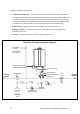
Listed below are common components in a
Central Heang system. Refer to the
diagram on the next page.
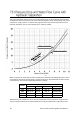
• Expansion Tank — A properly sized
expansion tank charged to 2 PSI (14 kPa)
below the cold system pressure is
required to limit pressure changes in the
heang system. When replacing an
expansion tank, consult the expansion
tank manufacturer for sizing.
• Air Separator — An air separator is
needed on the central heang supply
side of the system to remove any air
that may be present in the piping.
• Pressure/Temperature Gauge — The
current pressure and temperature will
alternately be displayed on the boiler
control panel. A port for an external
gauge is present in the Primary-
Secondary Heang Kit accessory oered
by Rinnai.
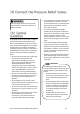
• Pressure Relief Valve (PRV) — A PRV
located directly on the supply side of the
boiler is required. The PRV must be 3/4
in. with at least 30 PSI (207 kPa) and a
maximum of 45 PSI (310 kPa). A 30 PSI
(207 kPa) PRV is supplied with the
boiler. A port for the central heang PRV
is present in the Primary-Secondary
Heang Kit accessory oered by Rinnai.
• Oxygen Eliminaon — The boiler may
only be installed in a pressurized closed-
loop heang system, free of air and
other impuries. If using oxygen
permeable tubing in the central heang
system, a plate heat exchanger is
necessary to isolate the tubing and
boiler.
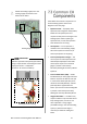
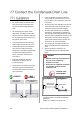
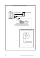
Plumb the heang supply line to the
heang supply connecon on the
boom of the boiler.
Heang Supply Connecon
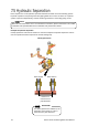
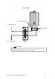
Hydraulic separaon with primary/secondary
piping is required when connecng the water
supply (see secon “7.5 Hydraulic
Separaon” for more informaon).
IMPORTANT
Primary/Secondary Piping