Operation / Installation Manual Rinnai Continuous Flow Water Heaters To Suit Water Heater Models - INFINITY 32 INFINITY 26 INFINITY 26i INFINITY 20 INFINITY 16 INFINITY ENVIRO 32 INFINITY ENVIRO 26 B16 B20 B26 HD250e HD200e HD200i HDC211e HDC211i REU-VRM3237WG REU- VRM2626WG REU-VRM2632FFUG REU-VRM2024WG REU-VRM1620WG REU-KM3237WD REU-KM2635WD REU-VR1620WB REU-VR2024WB REU-VR2626WB REU-VRM3237WC REU-VRM2632WC REU-VRM2632FFUC REU-KM3237WDC REU-KM3237FFUDC This appliance shall be installed in accordance wi
TABLE OF CONTENTS REGULATORY INFORMATION..................................................................................1 WARNING ABOUT HOT WATER ...............................................................................1 FEATURES AND BENEFITS ......................................................................................2 IMPORTANT INFORMATION .....................................................................................3 OPERATION WITHOUT CONTROLLERS...................................
REGULATORY INFORMATION Your Rinnai Continuous Flow water heater has been certified by the Australian Gas Association. The A.G.A. Certification Number is shown on the data plate. This Appliance must be installed correctly by an authorised person. The installation of gas, water, and electricity must conform to local regulations. The installation must also comply with the instructions supplied by Rinnai. All dimensions referred to in these instructions are in millimetres, unless otherwise specified.
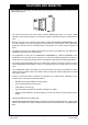
FEATURES AND BENEFITS Congratulations on purchasing the latest technology temperature controlled Rinnai continuous flow water heating system. • The Rinnai Continuous Flow water heater products NEVER RUN OUT of hot water. Whilst electricity, water and gas supplies are connected, hot water is available whenever hot water taps are open. • Built into the main micro-processor is the facility to LIMIT THE MAXIMUM TEMPERATURE of the hot water supplied. The water temperature may be limited to various values.
IMPORTANT INFORMATION NOTE The range of Rinnai continuous flow water heaters referred to in this manual are incompatible with solar water heating systems. A dedicated range of solar compatible continuous flow water heaters is available from Rinnai. OFF! Always check water temperature carefully before use. Refer to the WARNING ABOUT HOT WATER on "page 1" of this manual for important safety information. At low water flows, the hot water unit may extinguish without warning.
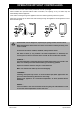
IMPORTANT INFORMATION S O L V E N T Max. 43°C Whilst hot water outlets are open the set temperature may be lowered. However they cannot then be raised above 43°C. In addition transfer of 'priority' between controllers is not possible. These are safety features. To clean your water controller(s) use a soft damp cloth with a mild detergent. Do Not use solvents! 49°C 50°C There is no need to turn the water controller(s) off after use.
OPERATION WITHOUT CONTROLLERS Rinnai Continuous Flow water heater products do not use a pilot light. When installed and operated without water controllers, the opening of any hot water tap will automatically start the appliance. Once water is flowing through the appliance the burner will be ignited by electronic ignition. When the hot water tap is closed and water flowing through the appliance has stopped the burner flame will extinguish.
GENERAL WATER CONTROL INFORMATION MAXIMUM DELIVERY TEMPERATURES Rinnai continuous flow water heaters are factory pre-set to various maximum delivery temperatures depending on model and their intended application. For the majority of applications, the factory preset temperature is appropriate. In the unlikely event this is not the case this setting can be increased or decreased by an authorised person such as a licensed plumber. NOTE This does not apply to “50 degree compliant” or “Solar” models.
GENERAL WATER CONTROL INFORMATION Remote water controllers allow precise temperature control by the user. When used correctly, the hot water unit will deliver the selected temperature, even when the water flow is varied, or more than one tap is in use. Each water controller can be individually programmed, however the water heater can only deliver one set temperature at any time.
UNIVERSAL WATER CONTROLLERS ABOUT THE UNIVERSAL WATER CONTROLLER (MC-91Q) W AT E R H E AT E R 'In U se' IN D IC AT O R P R E H E AT IN D IC AT O R Indicates that a water heater is in operation and deliverin g hot water. Indicates that the Smartstart® preheater (when fitted)is activated. P R E H E AT B U T T O N Used to start and stop the Smartstart® preheat unit (when fitted), See Smartstart® Operation on page 16. D IG I TA L M O N I T O R I n d i c a t es t h e t e m p e r a t u r e selected.
UNIVERSAL WATER CONTROLLERS HOW TO USE TWO OR MORE UNIVERSAL WATER CONTROLLERS TURNING ON THE WATER CONTROLLERS If the controllers are switched off (No digits displayed in the digital monitor window) press the On/Off button once at any controller. The ON indicator on the desired controller will illuminate, indicating that the hot water unit will be ready to supply hot water once a hot water tap is opened.
DELUXE BATHROOM WATER CONTROLLERS ABOUT THE DELUXE BATHROOM WATER CONTROLLER (BC-100V) W AT E R T E M P E R AT U R E IN D IC AT O R Indicate s the selecte d hot water temperature. W AT E R L E V E L IN D IC AT O R Indicates Shower Saver / Bath Fill volume selected. S H O W E R S AV E R / B AT H F IL L IN D IC AT O R W ATER HEATER 'In U se' IN D IC A T O R Indicates that the water heater is in operation and delivering hot water.
DELUXE BATHROOM WATER CONTROLLERS SETTING THE SOUND OPTIONS To set the sound options press the 'Sound Volume' as follows: button and select the desired audible setting Voice High, Med, Low or Off, sets the voice prompt volume but does not affect the audible tones. Sound OFF, mutes all voice prompts and audible tones.
DELUXE BATHROOM WATER CONTROLLERS OPERATING THE SHOWER SAVER / BATH FILL FUNCTION The 'Shower Saver / Bath Fill' function allows a preset water volume and temperature to be selected and run automatically. NOTE No voice prompts will be available if the ‘Voice OFF’ or ‘Sound OFF’ options are selected. With ‘Sound OFF’ there will also be no audible tones.
DELUXE BATHROOM WATER CONTROLLERS The voice prompt will say "The hot water system is ready. Open the hot water tap”. Open the hot water tap for the relevant shower or bath. ON! COLD The ‘In Use’ indicator will illuminate on all Deluxe water controllers and the shower will run or the bath will start to fill. To Stop Shower Saver / Bath Fill Operation HOT If you wish to stop the water flow whilst the Shower Saver / Bath Fill function is in operation, simply press the 'Shower Saver / Bath Fill' button.
DELUXE KITCHEN WATER CONTROLLERS ABOUT THE DELUXE KITCHEN WATER CONTROLLER (MC-100V) WATER TEMPER ATURE INDICATOR SHOWER SAVER / BATH FILL INDICATOR Indicates the selected hot water temperature. Indicates that the Shower Saver / Bath fill function is operating. DIGITAL MONITOR UP AND DOWN BUTTONS WATER HEATER 'In Use' INDICATOR When in Normal mode these buttons are used to select the water temperature Indicates that the water heater is in operation and delivering hot water.
DELUXE KITCHEN WATER CONTROLLERS SETTING THE CLOCK The clock is a 12 hour AM/PM style display. To set the time press the 'Mode' button twice. This places the controller into clock setting mode and in the digital monitor the word ‘Clock’ will be displayed and the clock digits will flash. If this is the first time the clock has been set the starting time will be AM 12:00. Use the or buttons to select the desired time. Holding these buttons down continuously cycles the digits.
SMARTSTART® PRE-HEAT OPERATION ABOUT THE SMARTSTART® PREHEAT SYSTEM 7 3 5 6 7 3 4 3 7 8 1 2 5 2 1 2 1 8 6 4 8 6 4 1 PREHE AT BUTTON Used to start and stop 'Smartstart ®' preheater.
TROUBLESHOOTING • Your Rinnai Continuous Flow water heaters has a self diagnostic capability. If a fault occurs, an Error Code will flash on the digital monitor or status monitor* if you have water controllers. This assists with diagnosing the fault, and may enable you to overcome a problem without a service call. Please quote the code displayed when enquiring about service. *All models in the range covered by this manual have a “Status Monitor”, except B16, B20 & B26.
INTENTIONALLY BLANK PAGE Rinnai Australia 18 Operation Manual
INTENTIONALLY BLANK PAGE Rinnai Australia 19 Operation Manual
INSTALLATION MANUAL GENERAL INSTALLATION INSTRUCTIONS ..........................................................21 REGULATIONS ......................................................................................................................................... 21 APPLICABLE MODELS ............................................................................................................................ 21 APPLIANCE LOCATION ...............................................................................
GENERAL INSTALLATION INSTRUCTIONS REGULATIONS This appliance must be installed in accordance with: • Current AS/NZS 3000, AS/NZS 3500 and AS/NZS 5601 • Rinnai Installation Instructions • Local regulations and municipal building codes including local OH&S requirements Installation, Service and Removal MUST BE by an Authorised Person only. APPLICABLE MODELS These Installation Instructions apply only to the following Rinnai Continuous Flow Water heater models are listed on the cover page of this manual.
GENERAL INSTALLATION INSTRUCTIONS (All Models) This appliance must be placed as close as practicable to the most frequently used hot water outlet or outlets to minimise the delay time for hot water delivery. For installations where the distance between the water heater and the outlets is considerable, a flow and return system or the Rinnai Smartstart® system can be used which minimise the waiting time for hot water delivery.
GENERAL INSTALLATION INSTRUCTIONS MOUNTING THE APPLIANCE See Table 1, page 23 for individual appliance weights. The wall or structure on which the units are to be mounted must be capable of supporting these weights and the associated pipe-work. The top bracket has a keyhole slot so that the appliance can be positioned by hanging it on one screw, then the other screws can be secured. The appliance can be mounted directly against the wall or structure.
GENERAL INSTALLATION INSTRUCTIONS HORIZONTAL FLUE TERMINAL CLEARANCES Flue terminal Fan assisted flue appliance only Gas meter Electricity meter or fuse box Mechanical air inlet Min. Clearances (mm) Ref. Item Fan-Assisted Below eaves, balconies and other projections: a • Appliances up to 50 MJ/h input 200 • Appliances over 50 MJ/h input 300 b From the ground, above a balcony or other surface * 300 c 300 d Front a return wall or external corner * From a gas meter (M) (see 5.11.5.
GENERAL INSTALLATION INSTRUCTIONS HORIZONTAL OBSTRUCTIONS AS/NZS 5601 ‘Gas Installations’ stipulates a minimum horizontal clearance of 500 mm between a building structure and obstruction facing the terminal. For Rinnai external continuous flow water heaters such a building structure must ‘obstruct’ the full front cover height of the appliance, or extend vertically above and below the front cover.
GENERAL INSTALLATION INSTRUCTIONS APPLIANCE AND WATER CONTROLLER DIMENSIONS A B I G O J H F C D L K E N FITTING DIAMETER 470 470 350 350 350 350 283 283 194 194 194 251 670 670 530 530 530 600 722 722 571 571 571 636 115 115 87 87 87 96 100 100 105 105 105 110 75 REU-VRM2632WC REU-VRM2632FFUG REU-VRM2632FFUC 100~150 91~131 REU-VRM1620WG REU-VR1620WB 644 REU-VRM2024WG REU-VR2024WB 600 350 470 350 194 257~307 235~375 654 530 600 722 571 641 REU-VR2626WB 2
GENERAL INSTALLATION INSTRUCTIONS CO-AXIAL FLUEING FOR INTERNAL MODELS Rinnai internal models described in this manual must use the Co-Axial Rinnai FFU flue components. The use of non Rinnai FFU flue components may result in a dangerous situation and violates regulations. The FFU flue system must be installed in accordance with the ‘FFU Flue Installation Manual’ which is provided with the FFU flue terminal components FFWALLTERM or FFROOFCOWL.
CONDENSATE DRAIN (REU-KM’ MODELS ONLY) The INFINITY & HDC REU-KM’ range of water heaters generate condensate continuously at a rate of up to 5 litres per hour as a by-product of highly efficient gas burner system. This condensate must be drained via a pipe to a suitable point of discharge. Because the condensate is a by-product of gas combustion it is mildly acidic. For this reason copper tube and fittings MUST NOT be used as it will corrode.
CONDENSATE DRAIN (REU-KM’ MODELS ONLY) INTERCONNECTION OF CONDENSATE DRAIN LINES Condensate drain lines from multiple water heaters may be joined together provided they conform with the ‘INSTALLATION’ requirements on page 28.
WATER CONTROLLER INSTALLATION RINNAI WATER CONTROLLERS Water controllers are available as an optional extra. Universal and Deluxe water controllers can be used together and will function as described in the Operation Section of this manual. Please refer to page 7 to confirm the maximum number and combination of water controllers that can be fitted. NOTE Other manufacturers water controllers are NOT compatible with Rinnai water heaters. Water controllers MUST NOT be used with any Solar Boost water heater.
WATER CONTROLLER INSTALLATION 7. Remove protective film from the water controller face as shown in (Fig. 4) and replace face plate. 90 Ø20 Cable Access 83 41.5 Securing Screw Controller Cable 120 Outline of Water Control Film Face Plate Fig. 1 Face Plate Connector Fig. 2 Screw Fig. 3 Fig. 4 OPTIONAL PROGRAMMING FOR THE ‘UNIVERSAL’ WATER CONTROLLER (MC-91Q) QUESTION Are there four water controllers connected? IF NO: (You have three water controllers or fewer), go to Question 2.
WATER CONTROLLER INSTALLATION Fix the mounting bracket to the wall using the appropriate fixings. 4. Run the cable through the hole in the wall. 5. Carefully remove face plate from the water controller, using a screw driver (Fig. 2). 6. 7. 120 3. 128 Ø20 Cable Access Use the wall mounting bracket as a template to mark and drill 3 holes, locating the cable access as shown in (Fig. 1). Screw Securing Points 2.
WATER CONTROLLER INSTALLATION CONNECTING COMMUNICATION CABLES TO THE WATER HEATER Communication cables connect the water heater to water controllers and operate at an extra low voltage (12 Volts DC) which is supplied from the water heater. Communication cables are supplied with the water controllers (15m) and are fitted with spade terminals for connection to water heater. Up to two cables can be connected directly to the ‘Ezi connect’ cable connector at the water heater.
COMMISSIONING TESTING 1. Before final connection of the water heater purge gas, hot water and cold water supply lines. Swarf in either the gas or water supplies may cause damage. 2. Turn on gas and cold water supplies. 3. Test for water leaks and gas escapes near the unit. 4. Isolate gas supply. Remove test point screw located on the gas inlet connection and attach pressure gauge. 5. Turn the power 'on' at the power point socket and turn on gas. 6.
COMMISSIONING GAS PRESSURE SETTING The regulator is electronically controlled and factory pre-set. Under normal circumstances it does not require adjustment during installation. Make adjustments only if the unit is not operating correctly and all other possible causes for incorrect operation have been eliminated. Instructions for Gas Pressure Setting are to be found in the instruction pocket located inside the appliance front cover.
ACCESSORIES Recess Box: These allow the appliance to be recessed into the cavity of the wall saving precious space. Suitable for painting. Pipe Cover: These hide the plumbing pipe-work and valves underneath the appliance. Two pipe covers can be joined together for longer pipe-work. Security Cage: Protect the gas booster unit from theft and damage. Security Bracket: Prevent theft of the gas booster by securing it with the custom security bracket.