Installation and User Manual Infinity 26e and HD50e Continuous Flow Water Heater Important. Read these instructions carefully before attempting installation or use of this appliance. All work must be carried out by competent persons.
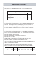
RINNAI UK WARRANTY As the purchaser of this high quality Rinnai Water Heater you are provided with the following conditional guarantee. Standard Use Infinity 26e Commercial Use HD 50e Heat Exchanger All Other Parts Parts Labour Parts Labour 3 Years 1 Year 3 Years 1 Year 5 Years* 1 Year 5 Years 1 Year Definition of Standard Use. The warranty period allocated under Standard Use is based on Domestic and Light Commercial hot water usage.
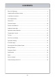
CONTENTS Rinnai UK Warranty .………………………………………………………………………… 2 Unpacking Rinnai Water Heater.…………………………………………………………… 4 Installation Instructions……………………………………………………………………… 5 Flue Requirements...………………………………………………………………………… 8 Dimensions...………………………………………………………………………………… 9 Technical Details.……………………………………………………………………………10 Features and Benefits……………………………………………………………………… 11 Important Information.……………………………………………………………………… 12 Operation without Remotes..
UNPACKING RINNAI WATER HEATER • After unpacking the appliance check for damage, if the heater is damaged contact your supplier immediately. Do not install a damaged appliance before checking with your supplier. • A heater accessories pack is inside the carton. One remote control is supplied with the Infinity 26e. The HD50e does not come with controllers because it is a commercial unit. It is compatible with them if they are required.
INSTALLATION INSTRUCTIONS IMPORTANT INFORMATION 1. Gas safety (Installation & Use) regulations 1998 are the ‘ Rules in force’ . In your own interest and that of safety, it is law that all gas appliances are installed by competent persons in accordance with the above regulations. Failure to install appliances correctly could lead to prosecution. Other persons should NOT attempt to install this equipment. 2. Unpack the appliance and check it carefully.
INSTALLATION INSTRUCTIONS - POSITIONING General Installation Information. External Installations. The Rinnai Infinity 26e and HD50e are for external mounting only. The unit is classed as a Category A3 flueless appliance as described by CEN CR1749. Although BS 5440 does not relate directly to heaters in this category the rules must be followed when positioning the appliance, especially with regard to other appliances, openings, and boundaries. Figure C.1 from BS5440-1:2000 is provided for your guidance.
INSTALLATION INSTRUCTIONS - CONNECTIONS Water Supply. Where the water supply pressure exceeds 10 bar, an approved pressure reducing device is required at the inlet of the appliance. To achieve the rated flow a minimum water supply pressure of 1.4 bar is required at the appliance inlet. The unit will operate at lower supply pressures but the rated flow will not be achieved. Contact Rinnai for 'gravity fed' or 'low pressure' hot water installations.
FLUE REQUIREMENTS - POSITIONING I Q Q P F Q D,E G N O C M B L N H A I H M J K Dimension Terminal Position Distance A Directly below an opening, air brick, opening windows, etc. 300mm B Above an opening, air brick , opening window, etc. 300mm C Horizontally to an opening, air brick , opening window, etc. 300mm D Below gutters, soil pipes or drain pipes. 75mm E Below eaves. 200mm F Below balconies or car port roof. 200mm G From a vertical drain pipe or soil pipe.
DIMENSIONS GAS COLD HOT A DIMENSIONS 40 50 41 Note:All dimensions are in mm.
TECHNICAL DETAILS Infinity Model Infinity 26e HD50e Units External External – Nat Gas Press Low 1.4 1.4 mbar Nat Gas Press High 7.9 7.9 mbar LPG Press Low 2.2 2.2 mbar LPG Press High 11.5 11.5 mbar Height 600 600 mm Width 350 350 mm Depth 235 235 mm Weight 21 21 kg Flue System Forced Exhaust Installation Temp. Range Controllers Temp.
FEATURES AND BENEFITS Congratulations on purchasing the Technologically Advanced, Temperature Controlled, Rinnai Hot Water System. • The Rinnai Infinity 26e and HD50e NEVER RUN OUT of hot water. As long as electricity, water, and gas supplies are connected, hot water is available when hot water taps are open. • Built into the main micro-processor is the facility to LIMIT THE MAXIMUM TEMPERATURE of the hot water supplied. The water temperature may be limited to various maximum temperatures.
IMPORTANT INFORMATION Excessively hot water is dangerous, especially for young children and the infirm. The water heater allows you to control the temperature of your hot water to safe levels. Water temperature over 50ºC can cause severe burns instantly or even death from scalding. Children, disabled and the elderly are at the highest risk of being scalded by excessively hot water. Always test the temperature of the water before bathing or showering.
IMPORTANT INFORMATION Always check water temperature before use. Hot water may go out without warning at low water flows. OFF Refer to warning about hot water on page 12 for important safety information. The Infinity 26e and HD50e control the water temperature automatically. For high temperatures it may reduce the flow. The water from the hot tap may be reduced after the temperature shown on the remote control is raised. The water flow may also vary with the temperature of the incoming water supply.
OPERATION WITHOUT REMOTES Rinnai Infinity and HD products have no pilot light and when installed without Temperature Controllers, the appliance will operate automatically as soon as a hot water tap is opened. The burner ignites with electronic ignition and the flame extinguishes as soon as water flowing through the appliance stops. Turn On by opening the hot water tap Rinnai Infinity water heaters without controllers are factory pre-set to a temperature limit of 55°C.
TEMPERATURE CONTROLS - GENERAL When deciding on the best position for the temperature controls, the following points should be taken into account. • Fit the controls out of reach of children (suggested height from the floor 1.5m.) • Avoid positions where the controllers will become hot. Do not fit them near stoves or ovens, or above radiators or heaters. • If possible, avoid exposure to direct sunlight or positions where bright lights will make the digital display difficult to read.
TEMPERATURE CONTROLS - INSTALLATION Universal Temperature Controller Outline of Remote Control MC-91-1A 83 2. Drill 3 holes in the wall as shown in fig.1, one for the cable and two for the securing screws. Ensure holes are drilled deep enough. Fit wall plugs if needed. (ensure controller is level.) Securing Screw 120 41.5 1. Determine the most suitable position for the temperature controller. ø20 Wire Hole 90 3.
TEMPERATURE CONTROLS - INSTALLATION Connecting One or Two Controllers 1. Isolate the power supply. 2. Remove the front cover from the Appliance (4 screws) fig. 1. 3. Thread the cable through the cable access hole at the base of the appliance. 4. Connect the spade connectors to the terminals marked "Remote Control" on the printed circuit board (fig.2). Polarity is not important. Either wire colour can be connected to either terminal. 5. Replace cover of the Appliance.
TEMPERATURE CONTROLS The purpose of a Temperature Controller is to enable the user to have complete control over the hot water supply. Used correctly, the hot water unit will supply hot water at the temperature selected, even when the water flow is varied, or when more than one tap is used. Adjustments to the operation of your hot water unit can be made with any of the Temperature Controllers. Each Temperature Controller can be individually programmed.
TEMPERATURE CONTROLS - OPERATING Remote temperature controllers are a feature that provides control over the water temperature. Rinnai Infinity and HD water heaters can be operated with 1, 2, 3, 4 or no temperature controllers. The Universal controller MC-91-1A comes as standard with all Infinity water heaters, and are optional for the HD range. Indicates the temperature selected. Error message flashes in the event of a fault. Used to select water temperature.
TEMPERATURE CONTROLS - OPERATING Using 1 Universal Temperature Controller. Press the On/Offbutton on the temperature controller. The ON indicator will glow on the Temperature Controller. This indicates that the heater is ready to supply hot water when a tap is opened. Adjusting Temperature Simply press the Hot Water Temperature Up or Down arrow button until the desired temperature is displayed on the digital display. To operate the heater, simply turn any hot water tap on.
TEMPERATURE CONTROLS - OPERATING Using 2 or more Universal Temperature Controllers. Switching the system ON. The hot water system and all controllers can be switched ON and OFF from any controller by pressing the On/Offbutton as shown. When the system is turned ON the water temperature display will be lit. During normal operation the system is left ON. Do not push the On/Offbutton when water is running. Using hot water. Ensure the system is switched On by verifying the temperature display is lit.
TEMPERATURE CONTROLS - OPERATING Using 4 Universal Temperature Controllers. You will need to activate the fourth controller. STEP 1: On the Master controller press and hold the Transfer and On/Offbuttons simultaneously (see fig. 2) until a “beep” is heard (approx. 5 seconds) STEP 2: Check that the display on all Four controllers is lit and displaying a temperature when switched on. If any ONE of the controllers displays two dashes (see fig. 1) in the display repeat STEP 1. Fig. 1 ON Fig.
TEMPERATURE CONTROLS - OPERATING Using High Temperature Display Controllers. You will need to program the Master controller if you want to display and use temperatures over 50°C. Programming only needs to be done on Master universal controllers; other universal controllers will not allow this, and Deluxe Kitchen Controllers are supplied already programmed to allow high temperatures. Temperatures in bathrooms should never exceed 50°C.
TEMPERATURE CONTROLS - OPERATING To turn off your hot water system. During normal operation the system is left on. To turn the system off simply press the On/Off button on any temperature controller (where fitted). This will shut the water heater down completely including the temperature controller digital display. The On indicator will go out. If hot water taps are opened when the Rinnai Infinity is off, cold water will flow from the taps.
TEMPERATURE CONTROLS - INFORMATION Do not push the On/Off button on the Master controller after transferring priority of temperature selection to a Secondary controller as the system will shut down. Temperature priority can not be switched to another controller when the water is flowing through the water heater.
TESTING CAUTION RISK OF ELECTRIC SHOCK 1. Purge gas, hot water and cold water supply lines before making the final connection of the water heater. Swarf in either the gas or water supplies may cause damage. 2. Turn on gas and cold water supplies. 3. Test for water leaks and gas escapes near the unit. 4. Isolate gas and electric supply. Remove test point screw located on the inlet gas valve connection inside the heater and attach pressure gauge. 5. Turn the power on at the switch and turn on gas.
GAS PRESSURE SETTING The working gas pressure on the water heater is electronically controlled and factory set. Under normal circumstances it does not require adjustment during installation. Perform this procedure only if the unit is not operating correctly and all other possible causes for incorrect operation have been eliminated. Contact Rinnai UK before attempting to alter the gas pressure. Failure to do so could void the warranty. 1. Turn 'OFF' the gas supply. 2. Turn 'OFF' 230V power supply. 3.
GAS PRESSURE SETTING 11.Adjust the regulator screw on the modulating valve (fig. 4) as required to the pressure below. N.G 1.4 mbar Propane 2.2 mbar fig. 4 Regulator adjustment screw access plug 12.Replace rubber access plug. 13.Set the appliance to 'Forced High' combustion by setting both no. 7 and no. 8 dipswitches of the bottom set of switches (SW1) to 'ON'. (fig.5) Ensure maximum water flow. OFF ON 14.Check the burner test point pressure. 15.
DIP SWITCH SETTING Dip Switch Positions Explained OFF ON SW1 1 2 3 4 5 6 7 8 - Computer Programming Temperature Temperature Temperature Temperature Temperature Combustion Combustion OFF ON SW2 1 2 3 4 - Gas Type Not in Use Computer Programming Not in Use LEGEND: Black Section indicates position of dip switch.
DIP SWITCH SETTING Infinity 26e and HD50e Temperatures - With or Without Remotes Connected OFF ON SW1 1 2 3 4 5 6 OFF ON SW1 1 2 3 4 5 6 OFF ON SW1 1 2 3 4 5 6 7 8 40 deg C 7 8 43 deg C 7 8 50 deg C HD50e only Temperatures - Remotes Connected OFF ON SW1 OFF ON SW1 OFF ON SW1 1 1 1 2 2 2 3 3 3 4 4 4 5 5 5 6 6 6 7 7 7 8 8 8 60 deg C 65 deg C 75 deg C OFF ON SW1 1 2 3 4 5 6 7 8 60 deg C OFF ON SW1 1 2 3 4 5 6 7 8 55 deg C If the remote was accidentally disconnected the unit would revert to 55C HD50e
ERROR MESSAGES Rinnai water heaters have the ability to check their own operation continuously. If a fault occurs, an error code will flash on the Digital Display if you have temperature controllers installed. This assists with diagnosing the fault, and may enable you to overcome a problem without a service call. Please quote the code displayed when enquiring about service. Code Displayed Fault Remedy - Noticeable reduction in water flow Inlet water filter needs to be cleaned.
ERROR MESSAGES Troubleshooting without controllers If you have not installed temperature controllers and experience the following symptoms, please carry out the suggestions below. If symptoms continue, please contact Rinnai for advice. Fault Remedy Heater does not attempt Check the power is on at the heater. to start at all. Check the cold water valve supplying the heater is open. Heater starts then shuts down immediately. Check the power is on.
RESTARTING THE RINNAI WATER HEATER Following a power cut the heaters should be restarted in this manner. Standard system. Single or multiple water heaters without remote controllers. The heaters will automatically reset without any user involvement. Single or multiple water heaters with remote controllers. The heaters will be required to be switched on using the ON/OFF button on a remote controller. Ensure that all taps/water outlets are closed and no water is flowing through heaters.
WIRING DIAGRAM COMBUSTION FAN A1 R FM Y W R Bk Y W BY-PASS FLOW CONTROL DEVICE 1 A 4 Br Or Y W Br R Or Y W 5 MODULATING VALVE CURRENT ADJUSTING G 1 G1 Temperature control HEAT EXCHANGER THERMISTOR P Gas pressure B4 OUTGOING WATER THERMISTOR W W R B Br Or Y Gy WATER FLOW CONTROL DEVICE D 12 P R R RR B2 E2 SOLENOID VALVE 1 Bk W P 1 1 OVERHEAT SWITCH B3 MAIN SOLENOID VALVE Br B E Y WATER FLOW SENSOR BC-70-2A OR MC-91-1A 5 Br R Bk R Bk Bk 3 R B C3 MC-70-2A OR MC-9
DIAGNOSTIC POINTS Diagnostic Points- To be read in conjunction with the wiring diagram. No.
SPECIFICATION Model………………………………………………..…....……….....Infinity 26e and HD50e Installation…………………………………………...………...……. External location only Fuel…………………………………………………..….……………... Natural Gas or LPG * Control………………………………………………….……………...……….…..Modulating Input……………………………………………………..……….……………......4.4 to 55 kW Exhaust type…………………………………………...……………....Forced Draught Flue Ignition………………………………………………...…………….…………...…..Electronic Burner……………………………………………………...…………………...Stainless steel Weight…………………………………………………...……….
NOTES 37
COMMISSIONING CHECK LIST For full details - Refer to Installation Instructions Attention Installer - have you checked: Gas supply pipe is purged of foreign matter before connection. For Hot and Cold cross connections i.e.
060 00012 39542 6 (V2632W-UK) U245-1480 Printed in Japan 2005.