INSTALLATION AND OPERATION MANUAL M-Series Condensing Boiler Wall-Mounted, Gas-Fired Solo Boiler Central Heating Boiler MODELS M060S M090S M120S M160S Certified to ANSI Z21.13 and CSA 4.9 WARNING If the information in these instructions are not followed exactly, a fire or explosion may result causing property damage, personal injury, or loss of life. • • • Do not store or use gasoline or other flammable vapors and liquids in the vicinity of this or any other appliance.
1. Welcome ........................................................................................................................... 4 2. Safety................................................................................................................................ 5 2.1 Safety Symbols ........................................................................................................................... 5 2.2 Safety Precautions ...................................................................
9. Power Supply .................................................................................................................. 57 9.1 Guidelines ................................................................................................................................. 57 9.2 Electrical Connections .............................................................................................................. 58 9.3 Post-Power Supply Connection Checklist ..............................................
1 Thank you for purchasing a Rinnai Condensing Boiler. Before installing and operating this boiler, be sure to read these instructions completely and carefully to familiarize yourself with the boiler’s features and functionality. • You must read the entire manual to • • • • properly operate the boiler. Keep this manual for future reference. As when using any appliance generating heat, there are certain safety precautions you should follow. See section “2.
2 WARNING • • • • • If the information in these instructions is not followed exactly, a fire or explosion may result causing property damage, personal injury, or death. Do not store or use gasoline or other flammable vapors and liquids in the vicinity of this or any other appliance. WHAT TO DO IF YOU SMELL GAS: − Do not try to light any appliance. − Do not touch any electrical switch; do not use any phone in your building. − Immediately call your gas supplier from a neighbor’s phone.
• Do not use this appliance if any part has • • • • • • • 6 been under water. Immediately call a licensed professional to inspect the appliance and replace any part of the control system and any manual gas control valve which has been under water. Do not use substitute materials. Use only parts certified for the appliance. Should overheating occur or the gas supply fail to shut off, turn off the manual gas control valve to the appliance.
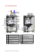
3 Topics in this section • • • • • • • Front View Bottom View Components Specifications Dimensions Accessories How to Remove the Front Panel The M-Series Condensing Boiler is a wall-mounted, gas-fired boiler designed to providing heating and domestic hot water. For complete boiler information, refer to the “Rinnai M-Series Condensing Boiler Installation Manual” supplied with the boiler, or visit rinnai.us.
Central Heating Supply Gas All items are field-supplied unless otherwise noted.
Exhaust Intake ❽ ❷ ❹ ❸ ❾ ❺ ⓫ ❶ Located behind #6 (Silencer) ❻ ❼ ❿ Located behind #6 (Silencer) 1 iCon Heat Exchanger 2 Burner Hood with Burner Cassette 3 Fan with Integrated Venturi 4 ⓬ ⓭ 8 Flue Gas Exhaust/Air Intake with Measuring Points 9 Automatic De-aerator Gas Valve 10 Control Panel 5 Ignition Unit 11 Pressure Sensor 6 Silencer 12 Modulating Pump 7 Condensate Tray 13 Condensate Trap Rinnai M-Series Condensing Boiler Solo Manual 9
Model M060S Dimensions - w, h, d 17 in. x 28 in. x 10 in. Weight M090S M120S M160S (439 mm x 699 mm x 264 mm) 64 lb (29 kg) 70 lb (32 kg) Appliance Type Wall-Mounted, Gas-Fired Solo Boiler Installation Type Indoor Ignition System Direct Electronic Ignition Heat Exchanger Type Heat Exchanger Surface Area iCon1 7.
Measurements: in. (mm) Vent Top Connections: 3 in. (80 mm) PP, 3 in. PVC, 3/5 in. Concentric, 2 in. (60 mm) PP, 2 in.
Gas Central Heating Supply Central Heating Return Connection 12 Connection Size with Provided Adapters Gas 3/4 in. NPT CH In (CH Return) 1 in. NPT CH Out (CH Supply) 1 in.
The following optional accessories are available for the Rinnai M-Series Condensing Boiler. CONDENSATE NEUTRALIZER Neutralizes the condensate generated by the boiler. SCALECUTTER REFILL CARTRIDGE SCALECUTTER Filters and reduces the amount of scale entering the boiler allowing for greater boiler longevity. BOILER TOOLKIT PN 809000024 Refill cartridge for the ScaleCutter filter assembly. Set of specific tools recommended for boiler service.
IMPORTANT Do not operate the boiler without the front panel installed. The front panel should only be removed for service/maintenance or replacing internal components. You Will Need: • 1 Philips head screwdriver Using a Philips head screwdriver, remove the 2 screws from the top of the boiler. TIP Be careful not to lose the screws. You’ll need them when reinstalling the front cover. 2 Lift the tab slightly above the peg. 3 To remove, carefully lift the panel up and off to release it from the boiler.
4 Topics in this section • • • • • • Installation Guidelines What You’ll Need Items Included Choose an Installation Location Mount the Boiler to the Wall Fill the Condensate Collector • The appliance, when installed, must be • THIS SECTION IS INTENDED FOR THE INSTALLER Installer qualifications: A trained and qualified professional must install the appliance, inspect it, and leak test the boiler before use. The warranty will be voided due to any improper installation.
• Ensure the wall is of sufficient strength to support the weight of the boiler, piping and any other components needed for installation; if it is not, please reinforce the wall as appropriate. • Operating limits of the boiler: Maximum boiler set point temperature: 185°F (85°C) Maximum operating pressure: 45 psi (3.
Carefully unpack your boiler system and verify the following contents are included. If any items are damaged or missing, contact your local dealer/distributor. Do not attempt to use any item that appears damaged. RINNAI CONDENSING BOILER Vent top with integrated 3 in. PP (80 mm) Connections Integrated Items Refer to section “3.3 Components” for a complete list of integrated parts.
When choosing an installation location, you must ensure that clearances will be met and that the vent length will be within required limits. Consider the installation environment, water quality, and need for freeze protection. Requirements for the gas line, water lines, electrical connection, and condensate disposal can be found in their respective installation sections in this manual. • Unsuitable heating system water can cause the formation of scale or sludge, which affects system efficiency.
Air surrounding the boiler, venting, and vent termination(s) is used for combustion and must be free of any compounds that cause corrosion of internal components. These include corrosive compounds that are found in aerosol sprays, detergents, bleaches, cleaning solvents, oil based paints/varnishes, and refrigerants. The air in beauty shops, dry cleaning stores, photo processing labs, and storage areas for pool supplies often contains these compounds.
Insert the mounting lip of the boiler onto the wall mounting bracket. Make sure the wall mounting bracket is attached to the wall and can hold the weight of the boiler before you fully let go. You Will Need: • • • Rinnai Condensing Boiler Wall Mounting Bracket Boiler Mounting Template Supplied by Installer: • • • Level Four screws for mounting bracket installation Screws for top and bottom bracket installation Use appropriate screws for type of wall construction.
5 Topics in this section • • • • • Guidelines Venting Installation Sequence Termination Considerations PVC Venting Safety Switch Venting Options • M-Series boilers can be installed in direct vent or non-direct vent applications. • When installed as Direct Vent, refer to the following section for a complete list of approved vent manufacturers and products: “5.4.1 Direct Vent: Approved Vent Manufacturers and Products.
• Avoid termination locations near commercial cooking exhaust. • Avoid termination locations near any air inlets. • You must install a vent termination at least 12 in above the ground or anticipated snow level. 1. Determine the termination method— horizontal or vertical, concentric, or twin pipes, etc. 2. Determine proper location for wall or roof penetration for each termination. 3. Install termination assembly as described in this manual or in the vent manufacturer’s installation instructions. 4.
Two venting options are available: Direct Vent and Non-Direct Vent (Room Air). Option 1 Direct Vent (Concentric and Twin Pipe) See Direct Vent section for complete details. Concentric Pipe Combustion air and exhaust vent directly through a single concentric connection. Hot exhaust exits through the interior tube, while combustion air enters through the outer layer. Twin Pipe Combustion air and exhaust vent directly through separate penetrations.
Following is a list of vent components and terminations for Direct Vent installations (concentric and twin pipe). Install the correct venting for your model according to the venting manufacturer’s instructions and the guidelines below. The information below is correct at time of publication and is subject to change without notice. Contact the vent manufacturer for questions related to the vent system, products, part numbers and instructions. Manufacturer Phone Web Site Ubbink 800-621-9419 www.rinnai.
Equivalent Length (ft) Vertical Horizontal Diagram Product Description Manufacturer Part Number Manufacturer 2 in./4 in. CONCENTRIC VENT TERMINATIONS (Continued) PVC Concentric Vent Kit 2 in. x 16 in. 20 52CVKGVS6502-28 PVC Concentric Vent Kit 2 in. x 28 in. 20 52CVKGVS6502-40 PVC Concentric Vent Kit 2 in. x 40 in. 20 CENTROTHERM ROYAL 52CVKGVS6502 ICRT2439 20 DURAVENT 2PPS-VKL/VK-TCL ECCO 2 in. x 4 in. Concentric Roof Termination 2 in. x 4 in.
Equivalent Length (ft) Vertical Horizontal Diagram Product Description Manufacturer Manufacturer Part Number 3 in./5 in. CONCENTRIC VENT TERMINATIONS UBBINK 3 in./5 in. CONCENTRIC VENT TERMINATIONS 223174PP 223176PP 223177PP 3/5 Condensing Horizontal Termination Kit 8.7 in. 3/5 Condensing Horizontal Termination Kit 12 in. 3/5 Condensing Horizontal Termination Kit 21 in. 5 223186PP 3/5 Condensing Horizontal Diverter Termination Kit 19 in.
Equivalent Length (ft) Vertical Horizontal Diagram Product Description Manufacturer Part Number Manufacturer METAL-FAB 3 in./5 in. CONCENTRIC VENT TERMINATIONS (Continued) 3CGRLSV Vertical Adapter 3CGRLSH Horizontal Adapter 3CGRVT Vertical Termination DURAVENT 6 5 3CGRHT ECCO 1 Horizontal Termination 16 3PPS-VKL/VK-TCL 3 in. x 5 in. Vertical Termination Cap KitConcentric 20 3PPS-HKL 3 in. x 5 in. Horizontal Termination Kit-Concentric 190388 3 in. x 5 in.
Equivalent Length (ft) Vertical Horizontal Diagram Product Description Manufacturer Part Number Manufacturer 2 in. TWIN PIPE TERMINATIONS IPEX DURAVENT CENTROTHERM 2 in. TWIN PIPE TERMINATIONS ISELL0287UV 2 in. 87° Long PPS-UV ISTT0220 2 in. Termination Tee ISLPT0202 2 in. Low Profile Wall Termination 2PPS-HTPL 2 in. Twin Pipe Termination 2PPS-HSTL 2 in. Single Horizontal Termination 2PPS-TBL 2 in.
Equivalent Length (ft) Vertical Horizontal Diagram Product Description Manufacturer Part Number Manufacturer 3 in. TWIN PIPE TERMINATIONS IPEX DURAVENT CENTROTHERM 3 in. TWIN PIPE TERMINATIONS ISELL0387UV 3 in. 87° Long PPS-UV ISTT0320 3 in. Termination Tee 6 ISLPT0303 3 in. Low Profile Wall Termination 5 3PPS-HTPL 3 in. Twin Pipe Termination 3PPS-HSTL 3 in. Single Horizontal Termination 3PPS-TBL 3 in.
Air Filter Screen Equivalent Length (ft) Vertical Horizontal Diagram Product Description VARIOUS 2 in. OR 3 in. SCHEDULE 40 PVC/CPVC TERMINATIONS N/A Tee 5 90° Elbow 5 45° Elbow 2.
The information below applies to Concentric and Twin Pipe. TERMINATION Clearance in Ref.
Between terminals at different levels 60 in. (1.52 m) Note: 24 in. (0.61 m) to wall or parapet 12 in. (0.30 m) 12 in. (0.30 m) 60 in. (1.52 m) vertically between terminals Inside Corner Between terminals at same level 12 in. (0.30 m) All terminations (horizontal and/or vertical) must terminate 12 in. (0.30 m) above grade or anticipated snow level. Vent Sizes Boiler Model Number Vent Lengths 2 in. X 4 in. 3 in. X 5 in.
The instructions below apply to concentric vent sizes 2 in. x 4 in. and 3 in. x 5 in. Remove the vent top (slightly twist counter-clockwise and pull up). Discard vent top if desired. Slightly twist counter-clockwise Horizontal Wall Terminations 2 in. x 4 in. and 3 in. x 5 in. Pull up Insert the concentric adapter and rotate clockwise until locked in place. Vertical Roof Terminations 2 in. x 4 in. and 3 in. x 5 in.
Horizontal Vent and Combustion Air Piping 12 in. (0.30 m) minimum 12 in. (0.30 m) minimum Wall Exhaust Zone 12 in. (0.30 m) minimum above combustion air opening 60 in. (1.5 m) minimum Exhaust Combustion Air 12 in. (0.30 m) above grade or anticipated snow level Roof Exhaust 12 in. (0.30 m) minimum 12 in. (0.30 m) above grade or anticipated snow level Combustion Air Combustion air termination not permitted in shaded area Vent Sizes • • Boiler Model Number Vent Lengths • 2 in. PVC 2 in.
This boiler is equipped with a 3 in. PVC pipe connection. With the use of a pipe reducer, installers can use a 2 in. pipe for the combustion air and exhaust. WARNING DO NOT apply PVC glues, solvents, or cleaners to the boiler’s combustion air or exhaust gasket connections. Failure to correctly assemble the components according to these instructions may result in property damage, personal injury, or death. Install 3 in. (80 mm) Polypropylene (PP) 1 Install 2 in. PVC or PP (60 mm) 1 Insert 3 in.
Slope horizontal exhaust 1/4 in. per foot towards the boiler. DO NOT slope combustion air pipe towards the boiler. CAUTION Rinnai cautions against installing the boiler in applications with venting in different pressure planes. It is possible to have poor performance with this installation. This configuration requires the use of a Concentric Vent Termination. This configuration requires the use of a Concentric Vent Termination. 2 in. or 3 in.
TERMINATION Clearance in Ref.
Room Air Vertical Termination of Multiple Boilers 12 in. (0.30 m) minimum Exhaust 12 in. (0.30 m) above grade or anticipated snow level Roof Exhaust Termination Clearances for Internal (Indoor) Room Air Applications 12 in. 12 in. (0.30 m) 60 in. (1.52 m) Vertically between terminals Inside Corner IMPORTANT • • 38 Installation of Room Air must use listed Category IV venting. All terminations (horizontal and/or vertical) must terminate 12 in. above grade or anticipated snow level.
ROOM AIR: INSTALLATION INSTRUCTIONS Insert air filter or elbow into 3 in. PVC intake air fitting. Air Filter Vent Sizes • • Boiler Model Number Vent Lengths Elbow 2 in. PVC 2 in. (60 mm) PP M060S, M090S • • M120S, M160S 3 in. PVC 3 in. (80 mm) PP M060S, M090S M120S, M160S 2 in.
WARNING • This boiler requires adequate combustion air for ventilation and dilution of flue gases. Failure to provide adequate combustion air can result in unit failure, fire, explosion, serious bodily injury or death. Use the following methods to ensure adequate combustion air is available for correct and safe operation of this boiler. Direct Venting is recommended in unusually tight buildings or in installation locations subject to significant negative air pressure.
Note: If ducts are used, the cross sectional area of the duct must be greater than or equal to the required free area of the openings to which they are connected. Louvers and Grills When sizing the permanent opening consideration must be taken for the design of the louvers or grills to maintain the required free area required for all gas utilizing equipment in the space.
CAUTION Rinnai cautions against installing the boiler in applications with venting in different pressure planes. It is possible to have poor performance with this installation. 2 in. or 3 in. 2 in. or 3 in. Schedule 40 PVC/CPVC Snorkel Termination Configuration Schedule 40 2 in. or 3 in. 2 in. or 3 in.
6 Topics in this section • • • Connect the Gas Supply Gas Operating Instructions Gas Pipe Sizing Reference Tables IMPORTANT • The boiler shall be installed such that the gas ignition system components are protected from water (dripping, spraying, rain, etc.) during appliance operation and service (circulator replacement, condensate trap, control replacement, etc.). • A sediment trap must be provided upstream of the gas controls.
Gas Fitting Connection 1. If the system requires a 3/4 in. connection, attach the 1/2 in. FNPT x 3/4 in. MNPT connection fitting to the gas fitting on the bottom of the boiler. 2. Check the type of gas and gas supply pressure before connecting the boiler. If the boiler is not of the gas type that the building is supplied with, converting the gas type of the boiler is necessary. A gas conversion kit is included with the boiler. Refer to section “14.
FOR YOUR SAFETY READ BEFORE OPERATING WARNING: If you do not follow these instructions EXACTLY, a fire or explosion may result causing property damage, personal injury or loss of life. A. This appliance does not have a pilot. It is equipped with an ignition device which automatically lights the burner. Do not try to light the burner by hand. B. BEFORE OPERATING smell all around the appliance area for gas. Be sure to smell next to the floor because some gas is heavier than air and will settle on the floor.
GAS PIPE SIZING CALCULATION WORKSHEET The gas supply must be capable of handling the entire gas load required at the location. Gas line sizing is based on gas type, the pressure drop in the system, the gas pressure supplied, and gas line type. For gas pipe sizing, refer to the National Fuel Gas Code, ANSI Z223.1/NFPA 54, or the Natural Gas and Propane Installation Code, CSA B149.1 Instructions: Enter values in empty boxes.
Natural Gas EXAMPLE Rinnai Model Gas Input: Pressure Drop 3.0 in. w.c. Intended use: Initial supply pressure of 8.0 in. w.c. or greater. Information in table obtained from NFPA 54, ANSI Z223.1 - 2015. Schedule 40 Metallic Pipe Inlet Pressure: Less than 2 psi Specific Gravity: 0.6 Nominal Pipe Size (in.
7 Topics in this section • • • • • • • Guidelines Instructions Common CH Components Piping Diagram for a Basic CH System Hydraulic Separation Connect the Pressure Relief Valves (DHW and CH) Connect the Condensate Drain Line • • • It is required to include an air separator on the central heating supply of the system. System piping should be insulated when freezing is a potential concern. All piping must comply with local, state, national or ASME code as appropriate.
Plumb the heating supply and return lines to the heating supply connection on the bottom of the boiler. It is required to use primary/secondary piping to the heating system. • Pressure/Temperature Gauge — The current pressure and temperature will alternately be displayed on the boiler control panel. A port for an external gauge is present in the Primary-Secondary Heating Kit accessory offered by Rinnai. • Pressure Relief Valve (PRV) — A PRV located directly on the supply side of the boiler is required.
CH System Common Components Diagram Low Water Cut Off (if required by local code) Pressure Relief Valve (supplied with boiler) Pressure Gauge (supplied with boiler) Air separator Primary-Secondary Heating Kit System Supply Dirt Trap Backflow preventer Expansion tank 50 Fill valve with pressure gauge Ball valve Rinnai M-Series Condensing Boiler Solo Manual System Return
IMPORTANT Optional Low Water Cut-Off (LWCO) Outdoor Sensor This schematic shows an example of a simple single zone system with primary/secondary piping by hydraulic separation. Pump Relay Thermostat Purge Station Heat Emitter This is not an engineering drawing; it is intended only as a guide and not as a replacement for professional engineering project drawings. This drawing is not intended to describe a complete system.
Rinnai requires hydraulic separation between the boiler and central heating system. Hydraulic separators allow for no pump curve matching or flow calculation; this is ideal for multi-temperature and multi-zone systems. Examples of Hydraulic Separation Closely spaced tees and low loss headers are common examples of hydraulic separators and can be used to separate the boiler loop from the central heating loop.
WARNING Water discharged from the pressure relief valve could cause severe burns instantly or death from scalds. • The discharge end of the line shall be plain (unthreaded) and a minimum of 3/4 in. nominal pipe diameter. The discharge line material must be suitable for water at least 180° Fahrenheit. • If a pressure relief valve discharges An approved pressure relief valve is required by the American National Standard (ANSI Z21.
• If the condensate drain pipe is closed or stuck, the drain water will come out from the side hole on the condensate drain pipe connection. If a floor drain is not available or the drain is above the level of the condensate drain, a condensate pump should be installed. A condensate neutralizer kit is available from Rinnai. The kit allows condensate to flow through neutralizing media that raises the pH of the condensate to a level that will help prevent corrosion of the drain and public sewer system.
Tools/Materials Required Multi-purpose grease or lubricant Verify Contents Item # Item Qty a Elbow with flexible pipe 1 b T-piece, elbow and flexible pipe assembly 1 c Flexible drain pipe 1 d Condensate drain inner tube 1 e Condensate drain outer tube 1 f Condensate collector cover 1 Instructions Reference Figure 1 for the following instructions. 1. Press and turn the assembly (3), with the elbow first, in the corresponding holes in the bottom plate of the boiler. 2.
8 Topics in this section • Guidelines • Indirect Tank Control Options The indirect tank temperature is controlled through either a thermistor or thermostat. This boiler provides DHW through an indirect tank. The boiler incorporates temperature control features for the boiler and indirect tank controls, including indirect tank heating priority. • Thermostat (Default): If thermostat control of the tank is desired, the thermostat connects to the yellow DHW screw terminal on the PC Board.
9 CAUTION Topics in this section • Guidelines Electrical Connections Post-Power Supply Connection Checklist • • • • • WARNING • Do not use an extension cord or adapter plug with the boiler.
Devices such as the room thermostat and outdoor temperature sensor are connected to the connection terminal. The connection terminals are located on the top and back of the controller. To access the controller, remove the front panel (see section “3.7 How to Remove the Front Panel” for detailed instructions).
10 IMPORTANT Topics in this section • • • Safety Precautions Instructions Air Purge Process THIS SECTION IS INTENDED FOR THE INSTALLER This boiler must be commissioned by a licensed professional. Installer qualifications: A trained and qualified professional must install the appliance, inspect it, and leak test the boiler before use. The warranty will be voided due to any improper installation.
3. Remove the vent pump screw. 4. Scroll to ON and press OK. 5. Scroll to 100% and press OK. 6. The boiler is now at maximum input. 4. Use a flat head screwdriver to ensure the impeller spins freely. 5. When the impeller spins freely and water exits though the vent port, the pump is ready for operation. 7. After the boiler has run for approximately one minute, the O2 percentages displayed on the combustion analyzer should match the ranges shown in the table below.
Step 3: Set the O2 at Minimum Input THIS SECTION IS INTENDED FOR THE INSTALLER 1. While still in service mode (as described in the previous step), use the scroll wheel to adjust to 0%. 2. Press OK. 3. The boiler is now at minimum input. 4. After the boiler has run for approximately one minute, the O2 value displayed on the combustion analyzer should read a value as shown in the chart on Nominal O2 Percentages table (see section Step 2: Set the O2 at Maximum Input). Example: If maximum input value is 4.
The boiler comes equipped with an automatic air purging process. This is a seven minute process designed to eliminate air in the water. The air purge program will start whenever the water pressure in the boiler gets below 10 PSI or when the boiler is powered on. The boiler will eliminate air from the water through the air vent on the heat exchanger. A minimum of 19 PSI is needed to complete the air purge process.
11 Complete the following checklist when boiler installation is complete. You should be able to answer YES to each question. If you answer NO, installation is not complete. Refer to the applicable section in this manual for additional information.
CONDENSATE DRAIN (Continued) Have you confirmed the condensate drain line is not connected with an air conditioning evaporator coil drain? This boiler has an integrated condensate trap.
12 Topics in this section • Start-Up Information • Control Panel • Basic Operation Settings • Parameter Settings • Outdoor Reset Control • Diagnostic Codes • Forced Hi/Low Fire Modes • Freeze Protection IMPORTANT • On initial startup of the system, it is necessary to put the boiler into an air purge process to remove all air from the system piping and boiler. The boiler will not immediately fire up and begin operation.
Slowly lower the protective panel on the front cover to access the control panel. Control panel ❼ CH Active ❺ ❸ ❶ ❷ ❹ ❶ ❻ Power (On/Off) Press to turn the boiler on or off. (I = On O = Off) ❹ Reset Press to reset a fault code. Turn the wheel left or right to scroll through available menu options ❸ Back Press to go back one screen. ❻ Chimney Active (Service Mode) Press to enter into service mode which allows adjustment of high fire/low fire and O2 settings.
When the boiler is turned on, the main screen (also called the home screen) appears in the display.
To change the language appearing on the boiler display, follow the steps below. To change the unit of measurements appearing on the boiler display, follow the steps below. 1. From the controller Home screen, press OK. 2. Turn the selector wheel to highlight Complete Menu. Press OK. 3. Turn the selector wheel to highlight Screen Settings. Press OK. 4. Language is highlighted. Press OK. 5. Turn the selector wheel to highlight the desired language and press OK. 6. The language is changed.
To turn the boiler on or off, press the Power switch. I = On O = Off 1 From the controller Home screen, press OK. 3 CH Settings is highlighted. Press OK. Home screen 2 Turn the selector wheel to highlight Complete Menu. Press OK. Rinnai M-Series Condensing Boiler Solo Manual 4 CH Setpoint Temp is highlighted. Press OK.
5 The option T set Z1 is highlighted. Press OK. For use with an external indirect tank. 1 NOTE: Z2 and Z3 are not active controls on this boiler. 6 70 Home screen Turn the selector wheel to until the desired target CH temperature appears on the display. Press OK. Available temperature settings (minimum to maximum): 68°F - 185°F (20°C - 85°C) 7 From the controller Home screen, press BACK. 2 Turn the selector wheel to the desired DHW setpoint temperature.
Boiler Parameters PARA Default Range Description 2.0.0 140°F 104 - 140°F DHW setpoint temp (also achieved by pressing BACK and turning dial on home screen) 2.0.3 194°F 176 - 194°F Max Water Temp (absolute max) Will limit outdoor reset curve settings 2.0.4 0 0-10,200 Will allow you to set higher than 10.2K but no effect 2.0.6 9°F/min 0-27°F/min How quickly boiler reaches setpoint from cold start ON/OFF AUTO function is the outdoor reset control.
Heating Parameters PARA Default Range Description 4.2.0 1 0=Low Temp 1= High Temp Outdoor reset curve presets 4.2.1 3 0=OFF 3=ON Thermoregulation: outdoor temperature reset Also available from AUTO function in main menu (CH) or 2.2.4 DO NOT USE 1,2, or 4 4.2.2 LT=0.8 HT=2.0 LT=0.2-1.0 HT=1.0=3.5 Slope of outdoor reset curve (see separate slides), depends on 4.2.0 setting 4.2.3 0 Depends on curve settings Heating curve offset (parallel shift) 4.2.
Service Parameters (Continued) PARA Unit Description 8.2.7 % Pump modulation (will never read above 90%) 8.2.8 kW Boiler power during operation (multiply by 3412 for BTU) 8.2.9 PSI Actual PSI (also on home screen) 8.3.0 °F CH Flow Setpoint, also called T-set 8.3.1 °F T1 (Supply temp) 8.3.2 °F T2 (Return temp) 8.3.3 °F T3 combi (DHW temp) 8.3.5 °F Outdoor temp sensor (also on home screen) 8.4.0 °F Indirect tank temp 8.5.0 Months Maintenance frequency 8.5.
To follow is an example of how to adjust parameters on the M-Series Boiler. Change the Altitude 1 From the controller Home screen, press the BACK and OK buttons at the same time for 7 seconds. 3 Turn the selector wheel to highlight Complete Menu. Press OK. Home screen All commonly adjusted parameters can be accessed in the Complete Menu. 2 Turn the selector wheel so that 007 appears as the technical code. The “007” Menu is where all parameters can be adjusted.
5 Option 2.0 General is highlighted. Press OK. 6 Turn the selector wheel to highlight 2.0.4 Altitude. Press OK. 7 Scroll to the desired altitude and press OK. 8 Press the Back button until the Home screen appears on the display. Note: Altitude is displayed in feet (ft) measurements. The parameter had now been updated to the set value.
Outdoor reset is a built-in function to help maximize the efficiency of the boiler. The design of this function is to adjust the target temperature of the boiler relative to the outdoor ambient temperature via the four outdoor reset curve options included in the boiler parameters. The outdoor ambient temperature is observed via the provided outdoor temperature sensor.
1. Remove the boiler’s front panel by removing the four screws that secure the panel. 2. Locate the HMI at the bottom of the unit. 3. Connect the outdoor sensor to the terminals shown. 4. Set parameters 4.2.0-4.2.6 as appropriate for your application (see section “12.4.1 Parameter Settings Table” for more information). Outdoor Temperature Sensor The boiler comes equipped with several outdoor reset curves, which are different target temperature lines dependent on the outdoor temperature.
Below are some typical target temperatures for various heat emitters. Type of Heat Emitter Typical Minimum Supply Temperature Typical Maximum Supply Temperature Hydronic Air Handler 120 - 140°F 140 - 180°F Unit Heater 130 - 140°F 160 - 180°F Base Board convectors 100 - 140°F 140 - 190°F Cast Iron / Panel Radiator 90 - 120°F 140 - 180°F Undermount Radiant 100 -120°F 120 - 150°F 80 - 90°F 110 - 130°F Poured concrete radiant *NOTE: These are basic guidelines.
WARNING Some of the checks below should be performed by a licensed professional. Consumers should never attempt any action that they are not qualified to perform. When the boiler detects an error, a 3-digit blocking or fault code appears on the controller display. • A blocking code is a temporary error that can be automatically corrected by the boiler. • A fault code requires the error to be reset and/or corrected for the boiler to go back into a normal operating mode.
Code Description Reason(s) Change in supply temperature 1P1 Flow Check 1 Failed of 12.
1 2 When an error occurs, the fault code and description appear on the display. To reset the fault code, press the RESET button. 4 5 6 3 The Reset in Progress message appears. The Fault Solved message appears. After the code is reset, the Home screen automatically appears.
1 From the controller Home screen, press the BACK and OK buttons at the same time for 7 seconds. 5 Turn the selector wheel to highlight 8.6 Error History. Press OK. Home screen 2 Turn the selector wheel so that 007 appears as the technical code. 6 7 3 Turn the selector wheel to highlight Complete Menu. Press OK. Option 8.6.0 Last 10 Errors is highlighted. Press OK. Scroll to view the last 10 errors.
Chimney Active (Service Mode) WARNING This section should be performed by a licensed professional. Consumers should never attempt any action that they are not qualified to perform. The Chimney Active (service mode) button puts the boiler into service mode which allows adjustment of high fire/low fire and O2 settings. To enter Chimney Active (service mode): 1 From the controller Home screen, press and hold the Chimney Active button for approximately 7 seconds.
The boiler is equipped with two different methods of freeze protection, one for the boiler itself and one for the system. If the Supply Temperature thermistor, T1, observes a temperature less than 47°F, the boiler pump will run for 2 minutes. The internal three way valve will alternate every minute to ensure circulation through both the primary heat exchanger and the plate heat exchanger.
13 Topics in this section • • • Owner Maintenance Licensed Professional Maintenance Test the Ignition Safety Shut Off Device WARNING If you encounter a problem that is difficult to solve, stop the operation and immediately contact a licensed professional. WARNING • • • • Maintenance is required to maintain safe operation of the boiler. The boiler must be inspected annually by a licensed professional. Repairs and maintenance shall be performed by a licensed professional.
TWO YEAR SERVICE Vent System • Inspect for blockages or damage. • Inspect vent screen or room air filter (if using) for debris and blockages. Clean if needed. Fan and Motors Clean dust and dirt from fan and motor (motors are permanently lubricated and do not require lubrication). Controller Check diagnostic code history. Pressure Confirm the pressure is within the proper range (between 17-26 PSI). If the pressure is lower than the specified range, add water until in the proper range.
Snow Accumulation • Verify the area around the flue terminal is free of snow and ice. The boiler will Freeze Protection • Freeze protection for new or existing systems must use glycol that is specially Coast Area Installations Installations located in or near coastal areas may require additional maintenance due to corrosive airborne ocean salt. If corrosion is observed on the body of the boiler, the boiler shall be inspected to ensure proper operation and repaired or replaced, if necessary.
1. Ensure the boiler is not currently firing and the flame rod is not hot. 2. Remove the boiler front panel. 3. Disconnect the wiring connection from the flame rod (located on the left side of the boiler). Boiler left side WARNING Remove the wiring connection Do not touch the inside of the wiring connection while it is disconnected. 4. On the control panel, press and hold the Service Mode button for approximately 7 seconds. 5. The boiler initiates one start-up attempt and four restart attempts.
14 Below is a list of approved system cleaners, inhibitors, and antifreezes for use in hydronic plumbing systems utilizing Rinnai boilers.
When replacing an existing boiler, the heating system shall be flushed with an approved system cleaner before the new boiler is added to the system. If the old boiler has already been removed, a bypass must be piped in when the new boiler is installed to facilitate the flushing of the system. The Rinnai boiler must be isolated from the system while the system is flushed. No system cleaner should ever enter the boiler heat exchanger due to its caustic nature which could damage the heat exchanger.
Boiler Casing 50 Item # Description Part Number Quantity M060S M090S M120S M160S 10 Boiler Mounting Bracket 809000161 1 1 1 1 12 Front cover 809000145 1 1 1 1 13 Screw M5 x 12 mm 809000019 2 2 2 2 14 Hinge 809000146 2 2 2 2 50 2-pipe adapter 802000005 1 1 1 1 51 3 in. PVC adapter 802000006 2 2 2 2 53 Measurement port plug 808000024 1 1 1 1 54 Gas valve screw plug 809000148 1 1 1 1 55 3/5 in.
Heat Exchanger 92 Rinnai M-Series Condensing Boiler Solo Manual
Heat Exchanger (Continued) Item # Description Part Number Quantity M060S M090S M120S M160S 30 Screw M5x16 809000015 2 2 2 2 31 Gasket 808000037 1 1 1 1 32 Burner hood 806000035 1 1 - - 806000036 - - 1 1 33 Gasket kit 806000037 1 1 - - 806000038 - - 1 1 34 Burner 806000032 1 1 - - 806000033 - - 1 1 36 Electrode gasket 805000062 1 1 1 1 37 Heat exchanger 807000169 1 1 - - 807000170 - - 1 1 38 Condensate tray gasket 807000135 1 1 -
Hydraulic Parts/Pipes 94 Rinnai M-Series Condensing Boiler Solo Manual
Hydraulic Parts/Pipes (Continued) Item # Description Part Number Quantity M060S M090S M120S M160S 79 Condensate collector kit 807000140 1 1 1 1 80 Condensate drain kit 807000141 1 1 1 1 81 Condensate drain o-ring Ø28.25 x 2.62 mm 807000142 1 1 1 1 82 Condensate drain inner tube 807000143 1 1 1 1 83 Condensate drain tube o-ring Ø37.69 x 3.
Electrical Components 96 Rinnai M-Series Condensing Boiler Solo Manual
Electrical Components (Continued) Item # Description Part Number Quantity M060S M090S M120S M160S 142 Ignition control box 805000060 1 1 1 1 146 controller casing/back 809000152 1 1 1 1 147 PC Board 805000055 1 1 1 1 148 Key pad 805000067 1 1 1 1 149 Controller casing/front 809000153 1 1 1 1 150 Hinge support 809000154 2 2 2 2 152 Fuse 4A (250V) 805000068 1 1 1 1 Screw terminal-white 805000069 1 1 1 1 Screw terminal-blue 805000071 1 1 1 1 S
IMPORTANT Primary/secondary piping is necessary in the following applications: • When using external pumps • Large zoned systems • High flow applications • Systems with high differential pressures • Systems with high pressure drops For pressure curve information, refer to the following sections in the Appendix. • 14.8 CH Pressure Drop and Flow Curve • 14.9 DHW Pressure Drop and Flow Curve Legend: Refer to the legend below for the system applications shown in this section.
PC Board Wiring for the above application example Low Water Cutoff (If Required) Zone Control Pump Thermostat Outdoor Temperature Sensor Rinnai M-Series Condensing Boiler Solo Manual 99
PC Board Wiring for the above application example Zone Valve 1 Low Water Cutoff (If Required) Zone Control Zone Valve 2 Zone Valve 3 Pump Thermostat 1 Thermostat 3 Outdoor Temperature Sensor Thermostat 2 100 Rinnai M-Series Condensing Boiler Solo Manual
PC Board Wiring for the above application example Low Water Cutoff (If Required) Zone Control Air Handler Control Pump Outdoor Temperature Sensor Thermostat Rinnai M-Series Condensing Boiler Solo Manual 101
PC Board Wiring for the above application example Pump 1 Low Water Cutoff (If Required) Zone Control Pump 2 Pump 3 Thermostat 1 Thermostat 3 Outdoor Temperature Sensor Thermostat 2 102 Rinnai M-Series Condensing Boiler Solo Manual
PC Board Wiring for the above application example Pump 1 Low Water Cutoff (If Required) Zone Control Pump 2 Pump 3 Thermostat 1 Rinnai M-Series Condensing Boiler Solo Manual Thermostat 2 Outdoor Temperature Sensor 103
This boiler is configured for Natural Gas only. To convert to Propane Gas, follow the instructions in this section. WARNING • • The conversion kit shall be installed by a qualified service agency in accordance with the manufacturer’s instructions and all applicable codes and requirements of the authority having jurisdiction. The information in these instructions must be followed exactly to minimize the risk of fire or explosion or to prevent property damage, personal injury or death.
1. Confirm that the inlet gas pressure is between the minimum and maximum pressures allowed for this boiler. 2. Disconnect electrical power to the boiler. 3. Turn off the boiler’s gas supply by turning off the gas control valve. 7. Remove the gas line and place aside. Gas line removed Gas line 4. Remove the boiler’s front panel. For details, see sections “3.7 How to Remove the Front Panel”. 5.
9. Remove the Liquid Propane restrictor in the gas venturi. 14. Remove the front housing of the PC Board. 15. Insert the EEPROM key (included with conversion kit) into the connector on the PC Board. 10. Replace the yellow gasket into the gas venturi. 16. Reattach the PC Board front housing and screw terminals. 17. Connect electrical power and power up the boiler. 18. The Airpurge active screen appears on the boiler display. 11. Reconnect the gas valve, gas venturi connections and gas line. 12.
20. The Flash Memory Detected screen appears. Select COPY and Press OK. 23. After a few seconds, the boiler automatically turns on and goes into Airpurge active mode. Your psi values may differ than the values shown in image. 21. The following screen appears indicating data parameters have been copied to the Mainboard. 24. To remove the EEPROM key from the PC Board: a. Disconnect power to the boiler b. Remove the front housing of the PC Board. c. Remove the EEPROM key from the connector. 25.
Rinnai M-Series Condensing Boiler Solo Manual
Rinnai M-Series Condensing Boiler Solo Manual 109
Pressure Loss (Feet of Head) 30 25 20 15 10 5 0 0 1 2 3 4 5 6 7 8 9 Water Flow (GPM) * Pressure drop curve applies to all M-Series Condensing Boilers (M060C, M090C, M120C and M160C).
Outdoor Reset Sensor (T4) Temperature (°C) -10 -9 -8 -7 -6 -5 -4 -3 -2 -1 0 1 2 3 4 5 6 7 8 9 10 11 12 13 14 15 16 17 18 19 20 21 22 23 24 25 26 27 28 29 30 35 40 NTC1k (25°C) Temperature (°F) 14.0 15.8 17.6 19.4 21.2 23.0 24.8 26.6 28.4 30.2 32.0 33.8 35.6 37.4 39.2 41.0 42.8 44.6 46.4 48.2 50.0 51.8 53.6 55.4 57.2 59.0 60.8 62.6 64.4 66.2 68.0 69.8 71.6 73.4 75.2 77.0 78.8 80.6 82.4 84.2 86.0 95.0 104.0 Resistance (Ω) 4.574 4.358 4.152 3.958 3.774 3.600 3.435 3.279 3.131 2.990 2.857 2.730 2.610 2.496 2.
The following information is required by ANSI Z21.13: If a boiler is removed from a common vent system, the common vent system is likely to be too large for proper venting of the remaining appliances connected to it. The instructions shall include the test procedure set forth below: At the time of removal of an existing boiler, the following steps shall be followed with each other appliances remaining connected to the common venting system are not in operation. 1.
FOR GAS MODELS SOLD IN MASSACHUSETTS NOTICE BEFORE INSTALLATION: This direct-vent appliance must be installed by a properly trained licensed professional. If you are not properly trained, you must not install this unit. IMPORTANT: In the State of Massachusetts (248 CMR 4.00 & 5.
Limited Warranty for M-Series Boiler Models Boiler Models: • • Combi: M060C, M090C, M120C, M160C Solo: M060S, M090S, M120S, M160S What Is Covered? The Rinnai Standard Limited Warranty covers any defects in materials or workmanship when the product is installed and operated according to Rinnai written installation instructions, subject to the terms within this Limited Warranty document. This Limited Warranty applies only to products that are installed correctly in the United States and Canada.
How Do I Get Service? For the name of a trained and qualified professional, please contact your place of purchase, visit the Rinnai website (www.rinnai.us), call Rinnai at 1-800-621-9419 or write to Rinnai at 103 International Drive, Peachtree City, Georgia 30269. Proof of purchase is required to obtain warranty service. You may show proof of purchase with a dated sales receipt, or by registering within 90 days of purchasing the product. To register your Rinnai Condensing Boiler, please visit www.rinnai.us.
Rinnai M-Series Condensing Boiler Solo Manual
Rinnai M-Series Condensing Boiler Solo Manual 117
800000065(04) 10/2019 Rinnai M-Series Condensing Boiler Solo Manual