
Installation Guide

Installation & Servicing Instructions Rinnai Q-Series
20
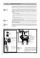
6.1.1 Plumbing Kit installation
Rinnai supplies specifi c Plumbing Kits with each boiler type, which must be fi tted
directly underneath the boiler on the supply and return pipe. Find in chapter 5.3 the
dimensions. Use of the Rinnai boiler without the plumbing kit will void the warranty.
To protect the entire heating system we recommend installing a dirt particle trap
in the return circuit. When the boiler is installed to an existing heating system
this trap is required. Use of a Y strainer is not permitted as a substitute for a
dirt trap.
- Install shut-off valves immediately before and after the dirt particle fi lter to allow
the trap to be cleaned.
- Position 3 (fi gure 8) is a garden hose thread boiler drain that can be used to drain
the boiler or add water treatment additives to the system such as inhibitors or
glycol.
- Position 4 (fi gure 8) is the supply connection for an indirect tank when used with
the optional 3-way valve kit.
- For information on locating the expansion tank and system fi ll, please see the
Rinnai Boiler Applications Manual.
Thoroughly fl ush all pipes and radiators. We recommend the use of a Rinnai
approved system cleaner. Please refer to the list of approved Rinnai system
cleaners in this chapter.
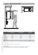
- Refer to the installation template and chapter 5.3 for the pipe connection dimensions.
The plumbing kit is not intended to support the weight of the piping. Appropriate
piping supports should be used to support all attached piping to the boiler and
plumbing kit.
NOTICE
i
NOTICE
i
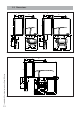
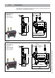
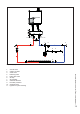
Plumbing Kit installation fi gure 8
5
9
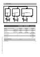
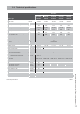
Compression fittings.
Parts:
1. Nut
2. Ferrule
3. Fitting
Fitting instructions:
1. Push the complete
fitting over the pipe as
far as possible. Ferrule
should be over the
pipe completely.
2. Turn the nut handtight
clockwise.
3. Use 2 wrenches, one
to hold the fitting on
its place, the other
for tighten the nut
clockwise in 3/4 turn.
21
3
1. Plumbing kit
2. Safety valve
3. Drain and Purge connection
4. DHW fl ow connection
in case of optional
internal 3 way valve
5. Bronze adapter fi ttings
6. Service valves*
7. Flow
8. Return
9. Pressure gauge*
2
1
3
4
6
8
7
* After installation of the plumbing kit to
the boiler the pressure gauge and both
handles of the service valves must be
mounted. Be sure the gauge is fi tted leak
free and that the handles are secured with
the supplied nuts.
NOTICE
i
NOTICE
i