
Installation Guide

Installation & Servicing Instructions Rinnai Q-Series
69
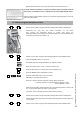
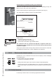
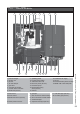
1 heat exchanger
2 ignition unit
3 fan unit
4 air inlet damper
5 gas valve
6 automatic de-aerator
7 ceramic burner cassette
8 DHW tank (Q175C)
9 operating panel
10 Control Tower (CMS)
11 water fi lter return CH
12 three-way valve (Q175C)
13 circulation pump
14 thermostatic mixing
valve (Q175C)
15 exhaust
T1 fl ow sensor
T2 return sensor
T3 DHW tank sensor (Q175C)
P1 water pressure sensor
Rinnai Q figure 45
4213
17
5
16
7
6
9
18
C E
13 14
15
W
G
10
T1
8
11
T2
T3
P1
KRF
16 combustion air supply
17 air box
18 CSA Data Plate (serial number)
19 ASME / NB / CRN data plate
G gas pipe
F fl ow connection central heating
R return connection central heating
C condensate pipe
E expansion tank pipe (Q175C)
15 Parts of the boiler
K cold water pipe (Q175C)
W hot water pipe (Q175C)
12
19