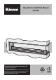
Operation & Installation Manual RF1800 This appliance shall be installed in accordance with: • Manufacturer’s Installation Instructions • Current AS/NZS 5601 AS/NZS 3000 • Local Regulations and Municipal Building Codes including local OH&S requirements This appliance must be installed, maintained and removed by an Authorised Person. For continued safety of this appliance it must be installed and maintained in accordance with the manufacturers instructions. All Rinnai gas products are A.G.A. certified.
Congratulations on the purchase of your RF1800 Decorative Gas Flame Effect appliance We trust you will have many years of enjoyment from your purchase. THIS MANUAL CONTAINS IMPORTANT INFORMATION. FOR SAFETY PLEASE READ CAREFULLY BEFORE PROCEEDING WITH ASSEMBLY, INSTALLATION AND OPERATION OF YOUR NEW FLAME FIRE AND GAIN A FULL UNDERSTANDING OF THE APPLIANCE.
OPERATION TABLE OF CONTENTS Before You Start 2 Safety 3 Safety Devices 4 Appliance Features 5 Operation Instructions 5 Operational Safety 5 Power Failure 5 Cleaning 6 When to call for Service 6 Service 6 Installation Table of Contents 7 Contacts 22 Rinnai 1 RF1800 OIM
BEFORE YOU START INSTALLATION REQUIREMENTS This appliance MUST BE installed by an authorised person. The installation MUST conform to local regulations. The installation MUST also comply with the instructions supplied by Rinnai. Service and removal MUST BE carried out by an authorised person. CERTIFICATION The Rinnai RF1800 has been certified by the Australian Gas Association. The Certification Number is shown on the appliance dataplate.
SAFETY WARNING DO NOT OPERATE THIS APPLIANCE WITHOUT READING AND UNDERSTANDING THESE INSTRUCTIONS. Taking time to familiarise yourself with the appliance’s features and operation will allow you to get the most out of your appliance for years to come. Please keep these instructions for future reference. Failure to comply with these instructions could result in a fire or explosion, which could cause serious injury, death or property damage.
SAFETY DO NOT sit or lean against the heater. IMPORTANT DO NOT post or allow children to post articles into the heater. DO NOT cover or place articles on this heater. DO NOT operate / install this heater in areas where painting is taking place, or in places such as hairdressing salons, where there may be fluff and dust, and where aerosols are used. DO NOT place articles on or against this appliance. DO NOT use or store flammable materials near this appliance. Keep flammable materials away from heater.
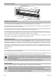
APPLIANCE FEATURES Heat Reflector Panels (Additional Rear and End reflector panels not shown) Outer Trim Glass Burner Glass Panels OPERATION INSTRUCTIONS To operate your appliance for the first time, ensure that the gas supply is on and that the appliance has been tested and commissioned by the installer (refer to the “Commissioning Checklist” on page 20).
CLEANING Regular cleaning of your appliance is important to keep it looking its best. Some points on cleaning: DO NOT attempt to clean appliance while in operation or when hot. WARNING DO NOT spray cleaners onto or around the burner as the liquid can get between the glass panels and cause water spotting. is important to keep the burner free from debris such as dust, insects and anything else that could cause a • Itblockage.
INSTALLATION TABLE OF CONTENTS Operation Table of Contents 1 Installation Safety 8 Specifications 9 Dimensions 9 Gas & Electrical Supplies 10 Clearances, Mantels, Surrounds, Recesses & Hearths 11 Ventilation 12 Flue Requirements 12 Engine Installation 14 Appliance Gas Connection & Commissioning 18 Final Checks 20 Trouble Shooting 20 Commissioning Checklist 20 Wiring Diagrams 21 Contacts 22 Rinnai 7 RF1800 OIM
INSTALLATION SAFETY WARNING This appliance must be installed by a suitably qualified person in accordance with local codes and AS/ NZS 5601 This is primarily a decorative appliance and has not been designed as a space heater This appliance has been tested to AS 4558 DO NOT operate this appliance without reading and understanding these instructions first This appliance is designed for installation into a timber framed construction and new or existing masonry installations NOT INTENDED FOR FIREPLACE INSERT
SPECIFICATIONS Models: RF1800L(N/P) “Left handed model”, RF1800R(N/P) “Right handed model” Gas Types: Natural Gas Propane Gas Description: Indoor Decorative Appliance Flue: 2x 150 mm stainless steel inner/ 200 mm galvanized steel outer Minimum of 2.4 metres of flue, 3.
NOTE The following installation instructions are for a left handed version of the appliance, when installing the right handed version dimensions and other references will need to be reversed. GAS & ELECTRICAL SUPPLIES B Gas Supply A suitable gas supply needs to be provided to the Left hand end of the appliance at the lower front corner of the installation cavity. The pipe sizing should be calculated to supply at least 40 MJ/h Allow sufficient pipe penetration to make the connection as shown right.
CLEARANCES, MANTELS, SURROUNDS, RECESSES & HEARTHS Clearances The appliance must be installed with the shown minimum clearances to combustible materials. 0 50 in) (m 500 (min ) Mantles 00 10in) (M A timber mantel may be installed above this appliance but must be within the grey area as shown here.
VENTILATION IMPORTANT This appliance is a decorative flame effect appliance, the space or room in which the unit is installed must have adequate fixed ventilation compliant with the requirements of AS/NZS 5601. For Decorative Gas Log Fires this requires that one or more openings with a combined free ventilation area of not less than 314 cm² shall be provided for each appliance.
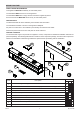
Flue Components A. RFPIPE150 900mm twin skin flue pipe ø 150mm inner / ø 200mm outer (approx 855mm when installed) B. RF1800YPIECE 1. Y piece collector box (1x) 2x ø 150mm inner / ø 200mm outer to 1x ø 200mm inner / ø 250mm outer. 2. 45° twin skin bends (2x) ø 150mm inner / ø 200mm outer. 3. 150mm flue pipe (2x) ø 150mm. 4. 200mm flue pipe over-wraps (2x) ø 200mm. (height approx 615mm when installed) C. RFCOWL200 Connection ø 200mm, Outer ø 350mm E.
ENGINE INSTALLATION Installation Options The appliance can be installed in 4 different ways. The basic appliance is supplied ready for installation as a fully open appliance where the appliance is open to the front and the glass sides are to the right and back. It is also available as a right hand appliance if required. IMPORTANT All appliances are shown with the open side foremost and glass panels to the back and right hand end. Even with the insulation kits installed, the glass panels remain in place.
Fully Open There must be a clear path for the flue to pass Allow at least 20mm gap for power and gas 250 715 Min Min 2183 1000 Min 468 o cladd ver ing 1000 Recommended Minimum 463 Min Flue is shown with optional flue gather and 200~250mm top flue section.
Fully Enclosed There must be a clear path for the flue to pass 2 63 m Flue is shown with optional flue gather and 200~250mm top flue section.
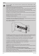
TOP FIXING In order to keep the top, unsupported end of the engine in line with the framing above, a support plate has been provided for fixing to the completed framing. 21 from cladding to back of support plate 115 Min In some installations the support plate may not be the most suitable solution. If this is the case then use another seismic type strap to hold the engine fast to the framing. Take care to make sure that the wall cladding will line up with the inside edge of the trim panel.
APPLIANCE GAS CONNECTION & COMMISSIONING CAUTION ISOLATE THE POWER AND GAS SUPPLIES BEFORE COMMENCING WORK ON THE APPLIANCE. Once the engine has been installed and fixed to the building the gas and electricity can be connected, however some installers elect to leave this until the decorating has been completed before finalising the installation.
Connecting Gas 1. Use the supplied Gas Connection Kit to connect the consumer piping to the appliance gas inlet. 2. Check for any crimps or kinks in the braided hose. Reconnect the gas supply and check for leaks. 3. Remove all the protective plastic film from both sides of the appliance. Gas Commissioning 240 VOLTS, RISK OF ELECTRICAL SHOCK! WARNING When performing the commissioning, the appliance electrical power will need to be connected.
FINAL CHECKS Check that the appliance operates properly making sure that all the supplied parts are used and properly installed. It is important that the customer is fully aware of how to operate the appliance properly and safely. Advise the customer to fully read the operation sections of this manual to understand how to get the best out of their appliance. Advise the customer of the need for regular servicing in order to maintain the warranty. Complete the Commissioning Checklist.
WIRING DIAGRAMS Appliance Wiring Diagram COLOUR WH BLU BRN GR OR WHITE BLUE BROWN GREEN / YELLOW ORANGE Connector Plug 5 Amp MAINS IN 230/240 V a.c. 50 Hz 10 AMP MAX BRN BLU 1 - EMPTY 2 - EMPTY 3 - EMPTY 4 - EMPTY 5 - BLK 6 - BLK 7 - BLK 8 - EMPTY 9 - EMPTY 10 - BRN 11 - BLU 12 - GR GR85 GAS CONTROL 12 PIN PLUG GR GR FLAME OR WH (HT LEAD) SPARK 1 GAS CONTROL 12 (SIT840 with 0.579.
CONTACTS Australia Pty. Ltd. Internet: www.rinnai.com.au E-mail: enquiry@rinnai.com.au ABN 74 005 138 769 Head Office National Help Line Tel: 1300 555 545* 100 Atlantic Drive, Keysborough, Victoria 3173 Fax: 1300 555 655* *Cost of a local call higher from mobile or public phones. Hot Water Service Line Tel: 1800 000 340 Tel: (03) 9271 6625 Fax: (03) 9271 6622 P.O.