CONTENTS Energysaver RHFE-556FTR Customer page 2 Installer page 21 Warranty ..........................1 Layout of appliance..........2 Features...........................5 Safety Points ....................7 Operation .........................9 Adjusting Temperature ...10 Economy Mode ..............10 Child Lock ......................11 Humidifier.......................12 Clock ..............................13 ON/OFF Timers .............14 Override .........................17 Remote Control..............
RINNAI WARRANTY OF QUALITY As the purchaser of this high quality model RHFE-556FTR product you are provided with the following warranty: Heat Exchanger Fan All other parts Free Parts 15 Years* 1 Year 1 Year * Full Heat Exchanger replacement (parts only) for all 15 years. This warranty does not cover cleaning and normal wear and tear, calls of this nature may be chargeable. Please check the fault finding charts on page 32, before asking for a service call.
GETTING TO KNOW YOUR NEW RHFE-556FTR REMOTE CONTROL BRACKET LOUVRE Warm air discharge duct. CONTROL PANEL Concealed panel with clock, room and preset temperature selection. Time, temperature and appliance error codes are shown here. HUMIDIFIER TRAY Built into the warm air discharge duct. Humidifies the warm air flow. ON/OFF SWITCH BOTTOM TRIM Pulls off to allow filling of humidifier tray. AIR FILTER Helps to protect the interior of the appliance and fan from dust particles.
–3– Selects energy saving function. Temp ・ Time Set ・ Room OVERRIDE Increases or decreases the temperature setting as well as changing hours or minutes. on Selects clock and/or Timers for adjusting or programming. SET TIMES Set times Timer 2 Timer 1 Clock off Indicates that clock or dual timer programme is being set. CLOCK ADJUSTMENT AND TIMER INDICATORS TIME/TEMP ADJUSTMENT AM PM Temporarily changes operation from ON to OFF or OFF to ON, until next programmed setting is reached.
Power source for operating remote control. REVERSE R2032 C OPEN FRONT Increases or decreases the temperature setting. TEMPERATURE ADJUSTMENT Stops heater manually. OFF ON Operates the heater manually. ON BUTTON OFF BUTTON TO REPLACE BATTERY Simply open the back of the remote control and replace Lithium battery.
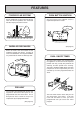
FEATURES FORCED FLUE SYSTEM PUSH BUTTON IGNITION Air for combustion is taken from outside the room and the flue products are exhausted outside, keeping the room air clean. Only one touch of the ON/OFF switch is required to operate the heater. EXHAUST ONE TOUCH AIR INLET WARM AIR DISCHARGE (See page 9) Warm air flows from the bottom of the appliance through the louvres, assisting in even heat distribution. An integral humidifier tray is built into the warm air discharge duct.
FILTER INDICATOR AUTO COMFORT When the fan filter becomes covered with dust and the temperature inside the appliance rises, the filter indicator will flash. The filter should be vacuumed at regular intervals to avoid unnecessary strain on the appliance. Ensures that the flow of warm air from the louvres is maintained at a comfortable volume during the warm-up period by a 8 step modulating convection fan, in conjunction with the thermostat, reducing cool draughts.
SAFETY POINTS Do not restrict the warm air discharge by placing articles in front of the heater. This appliance must not be used for any purpose other than heating. Do not spray aerosols whilst the heater is operating. Most aerosols contain butane gas, and can be a fire hazard if used near this heater when it is in use. Flue guard must be fitted if indicated on page 26. Do not allow curtains or other flammable or combustible materials to come into contact with the heater.
SAFETY POINTS Keep flammable materials, trees, shrubs, etc, away from the flue terminal. Do not allow anyone to post articles through the louvres. GAS Gasoline LPGAS Filter should be cleaned at regular intervals. See page 12. It is strongly recommended that a guard is fitted around the heater in rooms where there are young children, elderly, infir m or handicapped persons. Clean with vacuum cleaner, weekly. Do not allow young children or the infirm to sleep directly in front of the heater.
OPERATING YOUR NEW RHFE-556FTR ■ TO OPEN THE CONTROL PANEL Lift lightly in the centre of the lid where there is a catch. The control panel lid will then drop backward to an angle. LIFT ■ TURNING ON Press the ON/OFF button to operate the heater. The ON indicator will glow green. After approximately 20 seconds the spark generator will be heard before the burner ignites and the ON indicator glows red, indicating that the burner is alight. Warm air can be felt coming from the louvres 15 seconds later.
■ ROOM TEMPERATURE ADJUSTMENT The room temperature and pre-set temperatures can only be displayed and adjusted when the heater is running. 1 Press the “ ” button to increase the temperature setting or “ ” button to decrease the temperature setting.
■ CHILD PROOF LOCK The Child Proof lock will help to prevent accidental operation as well as small children from altering the controls. 1 To operate the Child Proof lock simply press the Child Lock button. The function is activated immediately and the Child Proof lock indicator will glow.
■ FAN FILTER To protect the room air fan from dust particles or lint, a filter is situated at the rear of the appliance. When this filter becomes blocked, the filter indicator will flash to indicate that it should be cleaned. Clean the filter weekly during the heating season to avoid unnecessary strain on the appliance. Do not remove filter when appliance is operating. When the filter requires cleaning, clean filter before using the appliance, or whilst the appliance is not operating.
SETTING THE CLOCK This Heater has an Integral Time Clock but can also be installed as part of a centrally controlled Time Clock System. To set-up the Integral Clock to operate the heater, proceed as follows (Ensuring that the Central Clock, if applicable, is ON):TIMER/CLOCK SET INDICATOR ON-OFF SWITCH INDICATOR DIGITAL DISPLAY ON-OFF SWITCH TIMER/TEMP ADJUSTMENT TIMER/CLOCK SET OPEN THE CONTROL PANEL – SEE PAGE 9. 1 As an example, let’s set the clock to 10:35 am.
PROGRAMMING THE TIMER(S) Before programming the Timers you must ensure that the clock has been set to the correct time. See page 13. As an example let’s programme Timer 1 to heat the room by 7:10 AM and finish at 9:00 AM. 1 Press the Set Times button twice. The Digital Display will show AM 6:00. Timer 1 indicator will flash. 2 Timer 1 Timer 2 Temp ・ Time Timer 1 Timer 2 Temp ・ Time 4 Press the Set Times button three times to lock in the programmed time. The Digital Display will show the current time.
OPERATING THE TIMER(S) Before operating the Timer(s), the clock time must be correct, and a starting time and finishing time for the Timer(s) must be programmed. See pages 13 and 14. The two Timers operate in the same way. This heater does not commence operation at the programmed starting time. It will attempt to heat a room by the programmed starting time. See Pre-heat page 16, for further explanation.
PRE-HEAT 1 This function operates automatically in conjunction with either of the Timers. When a Timer is selected, the heater may operate anywhere within an hour prior to the programmed starting time of the Timer. The Pre-heat function will heat a room to the pre-set temperature by the programmed On Time. This function is called Pre-heat due to the way it operates. The room temperature is sensed one hour before reaching the programmed time of either Timer.
OVERRIDE FUNCTION This function is intended to be used to manually override the current operation of the heater, For example; If the heater is in standby mode (i.e. between finishing time and starting time of a Timer). and the Override button is selected, then the heater will begin to operate, and heat the room. 1 To operate the Override simply press the Override button. The Override indicator will flash.
CARING FOR YOUR NEW RHFE-556FTR This appliance is controlled by a micro computer. If there is something wrong with the appliance then it will stop, as it is protected by the following safety devices. Ignition Safety Device Burner Safety Device Overheat Safety Device Power Failure Safety Device Power Surge Safety Device Fan Delay Safety Device Your RHFE-556FTR requires very little maintenance, simply clean the rear fan filter once a week and wipe the outer case and louvre section with a damp cloth.
PRE-SERVICE CHECK Before asking for a service call please check the following points. These points are part of the normal operation of the unit. ■ At Ignition: Heater does not operate. R Is the heater plugged in? Have the fuses or breaker blown at the switch board? Is there a power failure? Is the air filter blocked? Is anything blocking the outlet for the hot air? Is the flue blocked? Are Timers set? Clear Timers and operate again. Warm air does not flow when the burner lights.
ERROR MESSAGES The Energysaver 556FTR has the ability to check its own operation continuously. If a fault occurs, an Error Message will flash on the Digital Display of the control panel. This assists with diagnosing the fault, and may enable you to overcome a problem without a service call. Please quote the code displayed when enquiring about service. CODE DISPLAYED FAULT REMEDY Ignition failure Check gas is turned ON. Service call if repeated. Flame failure Check gas is turned ON.
INSTALLATION INSTRUCTIONS IMPORTANT SAFETY INFORMATION 1. Gas Safety (Installation & Use). Regulations 1998 are the ‘Rules in Force’. In your own interest and that of safety, it is law that all gas appliances shall be installed by competent persons in accordance with the above regulations. Failure to install appliances correctly could lead to prosecution. Other persons should NOT attempt to install this equipment. 2. This appliance is intended to be used to raise the temperature in a room or office etc.
INSTALLATION INSTRUCTIONS SPECIFICATION Input 6.4Kw (21840 Btu/h) Burner: Stainless Bunsen Type Ignition: Flue: Gas Control: Electrical Supply: Continuous Spark Gas Inlet: 1/2 inch BSP Connection Forced Flue (Components are supplied with appliance). Rinnai Electronic Modulating Controls. 230V, 50Hz. This appliance is fitted with a supply lead and 3 pin plug. ■ Remove parts from carton and check that all parts shown below are included in the installation kit.
LOCATION When positioning the heater the main points governing the location are: This heater is not designed to be built in. 1. Flueing 2. Warm air distribution This heater must not be installed where curtains or other combustible materials could come into contact with it. In some cases curtains may need restraining. See diagram for other recommended clearances. 300mm The flue is not designed to be positioned under floors, or below the level of the heater.
LOCATION Do not flue into natural draught flues or fireplaces, this unit can only be used with one of the six types of Rinnai flue kits. Do not flue unit into other rooms. Flue terminal must be outside. STANDARD INSTALLATION OF FLUE MANIFOLD. Diagram below shows minimum clearances and distances from obstructions. Also check local regulations. Flammable Wall 600mm Non Flammable 300mm 300mm 600mm When fitting the terminal beneath any ventilation opening i.e.
POSITIONING THE FLUE TERMINAL Q I Q Q P F D,E G Dimension N O C M B L N H A I H M J Terminal Position K Distance A Directly below an opening, air brick, opening windows, etc. 300mm B Above an opening, air brick, opening window, etc. 300mm C Horizontally to an opening, air brick, opening window, etc. 300mm D Below gutters, soil pipes or drain pipes. 75mm E Below eaves. 200mm F Below balconies or car port roof. 200mm G From a vertical drain pipe or soil pipe.
LOCATION Do not install the heater in an unusually dusty area. Cavity Opening R27 9 280 22 214 300 06 R2 217 φ80 Flue Hole Use a flue guard if the terminal is easily accessible to children. Check local regulations. Guards are available as an optional extra. Before drilling the flue hole, check for water and gas pipes as well as electric cables. Use an 80mm (8cm) drill for hole through wall. Guard MOUNTING TO WALL Assemble Angle Brackets to Back Spacer Top with screws provided.
SLEEVE AND MANIFOLD INSTALLATION METHOD FOR STANDARD WALLS 1. Dis-assemble Manifold from Sleeve. The flue consists of 3 parts, sleeve, inside connectors and tube, outside terminal; (disassemble by pulling hard on outside terminal and inner connections, then pull sleeve off outer terminal). Sleeve Connection Terminal 2. Adjustment of Sleeve Length. Measure wall thickness through previously drilled 80mm hole. End of sleeve should protrude 5-10mm from outside wall.
SLEEVE AND MANIFOLD INSTALLATION METHOD FOR STANDARD WALLS 5. Check rubber seal is in place on terminal. Terminal seal "TOP" mark "A" 6. Installation of Terminal Label From outside, insert terminal into sleeve with the “A” mark at the top. Left hand side fixing tie is marked “LEFT” (from inside). Fixing tie Terminal Cut (leave 20mm free) 7. Attaching Ties Pull hard on left and right hand side ties, clip ties over lugs inside sleeve. You should be able to pull ties 2 or 3 slots past the starting point.
FITTING UNIT AIR INLET HOSE 2. Fit the locking clamp over connection between sliding tube and manifold. Engage the hook and rotate it until it snaps against the body of the clamp. Manifold Manifold Inlet hose Flue outlet Sliding tube Hose clip Hook Detail of Hose clip Locking clamp Locking Clamp Plastic tie 3. Fit the screw clamp between the sliding tube and the flue elbow. Secure with the 4mm screw supplied. The flue outlet is now locked into position.
CONNECTING GAS AND ELECTRICAL SERVICES 1. GAS CONNECTION. Purge any air or swarf from the gas line. Connect up the appliance to the gas supply using a union service cock to facilitate servicing. Inlet connection size Gas (1/2 inch male BSP) Check gas soundness using leak detection fluid, not naked flame. Connection can be easily reached from right hand side rear of appliance. Remove bottom trim (pulls off). Remove louvres (6 screws) and front panel. 2. ELECTRICAL CONNECTION.
TESTING PRESSURE CHECKING PROCEDURE Caution – 230V inside appliance SW6 DIP SWITCH OFF ON OFF OFF NG 1. Check that SW6 (Dip switches) are correct for the gas type for which the appliance is to be used. (Refer to diagram opposite). 2. There are two test points, one on the heat exchanger, one on the gas manifold. Connect a pressure gauge between both test points. (Connect one side of the gauge to one point, the other side of the gauge to the other).
FITTING TOP SPACER + WALL CLIP ■ SECURE HEATER TO WALL Tighten all screws, fit fan filter. Fan filter Levelling screws(Adjustable legs) Fix angle bracket to back spacer with screws provided. Fix wall bracket to wall, so that the tongue of the anglebracket will fit into it, when the back spacer is fitted to the top of the heater. Up to 10 mm Adjustable Leg If necessary, the unit can be levelled using the adjustable legs under the front right and left hand side legs.
BLOCK AND WIRING DIAGRAM WIRING DIAGRAM RCR AC 24V MS SW6, DIP SWITCH SW1 FM, ADJUST SWITCH〔Hi〕 TB1 SW2 FM, ADJUST SWITCH〔Lo〕 SW3 POV, PRESSURE ADJUST SWITCH〔Hi〕 bk bk SUB-P.C.
FORCED FLUE HEATER EXTENSION KITS EXTENSION KIT PARTS AND INSTALLATION GUIDE FOT - 155 0.5m EXTENSION KIT FOT - 156 1.0m EXTENSION KIT FOT - 157 2.0m EXTENSION KIT FOT - 158 BENT ELBOW KIT FOT - 160 LONG FLEX TUBE 600 KIT • This extension set is to be used for installations requiring extra distance. MAXIMUM FLUE LENGTH 4.
※ When the appliance is installed using a flue extension that exceeds 1.8 metres you must change the link on the flue extension terminal block as shown. Terminal is located at the rear of unit next to gas inlet. 3 FOR DIRECT EXHAUST 2 USED FOR EXTENSION KITS 1 ■ TYPES COMPATIBLE WITH EXTENSION KIT RHFE-556FTR/556T INSTALLING AN EXTENSION KIT Installing an extension kit requires construction of an air line and the exhaust line.
1. How to connect exhaust pipes Exhaust pipe Exhaust pipe Fit inside Male end Female end Male end Pipe stopper B Pipe stopper A Female end Pipe stopper B To connect the exhaust pipes, fit the male end into the female end and clamp with pipe stopper A to prevent slipping. The exhaust pipe can be telescoped to the required length; do not cut it. Female end Male end Connect bent pipe Fit inside Pipe stopper A 2.
■ CAUTIONS 1. Maximum extendable length FOR BEST ROOM AIR HUMIDITY, KEEP WATER IN THE HUMIDIFIER TRAY. 2. To prevent water condensation Condensed water may accumulate here, and cause a blockage preventing combustion. • 4.5 Metres, 3 Bends • The bend where the hose and pipes leave the body is not counted. • The air intake hose should run along the exhaust pipe. 75mm slope(approximate) Less than 2.5m 3.
4. Wherever the air intake hose and exhaust pipe run sideways, try to have the exhaust pipe on top (to prevent the air intake hose from sagging onto the exhaust pipe).
DIMENSIONS 77 165 85 GAS CONNECTION WALL OPENING RANGE 06 AIR SUPPLY CONNECTION 280 134 214 300 50 554 R2 R279 280 217 36 245 632 750 SERVICE CONTACT POINT Rinnai UK 9 Christleton Court Manor Park Runcorn WA7 1ST tel: 01928 531 870 fax: 01928 531 880 – 39 – 556F-2191 01 / 06