Flue Installation Manual To Suit: Rinnai Aspiration (Australia) Rinnai Arriva (New Zealand) RHFE-750ETR Flame Fire Heater Installation shall be in accordance with: • Manufacturer’s Installation Instructions • Current AS/NZS3000, AS/NZS3500 & AS5601 • Local Regulations and Municipal Building Codes Installation, service and removal by an Authorised Person only. Proudly a member of the A.G.A. All our gas products are A.G.A.
TABLE OF CONTENTS IMPORTANT INFORMATION.................................................................................................. 3 DESCRIPTION OF FLUE SYSTEM......................................................................................... 4 Types of Flue Installations ............................................................................................................ 4 Flue System Transition Casting.....................................................................................
IMPORTANT INFORMATION The Rinnai Aspiration (RHFE-750ETR) Co-axial flue system is certified as a component of the Aspiration Flame Fire Heater. Only an Authorised person must install, service and remove the heater and flue system. The heater and the flue system shall be installed in accordance with: • The requirements of AS 5601 'Gas Installations' • Manufacturers installation instructions • Local and Municipal building codes • Any other relevant Statutory Regulation.
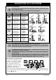
DESCRIPTION OF FLUE SYSTEM Types of Flue Installations IMPORTANT Options I Direct II A Vertical Extension II B Vertical Extension III A Vertical Extension III B Vertical Extension IV Sideways Extension V Down & Out Extension Consult the Rinnai Aspiration Flame Fire Customer Operation / Installation manual supplied with the heater. Use only Rinnai Aspiration flue components with this appliance.
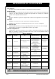
DESCRIPTION OF FLUE SYSTEM Components Flue Terminals • Two styles of flue terminal are available, a wall terminal and vertical terminal. Condensate trap • A condensate trap is required for any vertical flue system to ensure condensate generated in this section of flue during combustion is trapped and prevented from entering the combustion chamber of the Aspiration flame fire heater. Bends • Bends are available as a pair of 45° angle bends. If a 90° bend is required the 2 x 45° bends are joined.
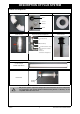
DESCRIPTION OF FLUE SYSTEM Photos of Components Pair 45° Bends Horizontal Wall Terminal Kit Universal External Wall Plate Spacer Universal Wall Plate End Grill Condensate Trap Vertical “On Wall” Flue Adaptation Kit Vertical Terminal Condensate Trap Stand Off Clip “On Wall” transition casting Not shown but also included: - Cable tie - Instructions - Container of ‘O’ Ring Grease Co-axial Flue Pipe (installed length 960 mm) Direct Flue Kit transition casting • IMPORTANT Rinnai Only the flue sys
DESCRIPTION OF FLUE SYSTEM • IMPORTANT Only the flue system components designated in this manual must be used. Components not designated in this manual, whether manufactured by Rinnai or otherwise, are not compatible and must not be used.
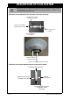
DESCRIPTION OF FLUE SYSTEM Exploded view of component assembly 25mm 15mm • IMPORTANT Rinnai Only the flue system components designated in this manual must be used. Components not designated in this manual, whether manufactured by Rinnai or otherwise, are not compatible and must not be used.
DESCRIPTION OF FLUE SYSTEM Use of Silicone Grease • The inner flue pipe joints are sealed with an 'O' ring seal. • To ease assembly, lubricate the 'O' ring on the inner pipes prior to assembly of components using the silicone based 'O' ring grease from the plastic jar included with the direct flue kit or the 'On Wall' transition kit. Configuration Limitations Flue system length is limited to 6.5 metres and up to 2 x 90 degree bends can be used.
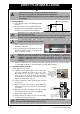
DIRECT FLUE INSTALLATION ‘Direct Flue’ Installation (Page 4 - Option I ) • Standard "Direct Flue kit" is suitable for walls up to 400 mm thick. • Flue can be cut to length if the wall thickness is less than 400 mm. • Flue can be extended if wall thickness is greater than 400 mm using additional lengths of NOTE Co-axial pipe. 1. Getting started Centre line of appliance a.) Select desired location for installing Aspiration flame fire. b.) The flue requires a hole of 100 mm diameter.
DIRECT FLUE INSTALLATION g.) Fit black plastic flue spacer to shortened flue outlet. h.) Fit small black plastic flue outlet grill to the newly cut inner flue pipe with the bars in a horizontal direction. i.) Slide newly cut shortened flue pipe through wall. j.) Slide the plastic external wall cover plate over the flue pipes on the outside of the wall, ensuring the ‘TOP’ symbol and mounting screw holes are on the top side of the flue.
DIRECT FLUE INSTALLATION g.) Cut the length of outer tube so it protrudes past external wall by 15 mm (as shown). h.) Cut inner flue pipe so it protrudes past the outer tube by 25 mm (as shown). 25mm 25 mm between end of alloy inner and outer tubes to ensure products of combustion are not drawn back into air intake. i.) Refit previously removed inner black plastic flue spacer. 15mm j.) Fit wall plate to wall, using the screws provided through the three countersunk holes molded in plastic wall plate.
DIRECT FLUE INSTALLATION Slide Tube b.) Fit flue slide tube into the flue system transition casting. Locking Clamp Direct Flue Transition Casting c.) Secure flue slide tube to the transition casting by use of the locking clamp which is supplied with the heater (Australia) or flue (NZ). Tighten screw to secure. Slide Tube from heater Locking Clamp The photo to the right shows the final assembly of slide tube and transition casting locked together by locking clamp. Transition Casting 6.
VERTICAL ON WALL FLUE INSTALLATION ‘Vertical On Wall’ Flue Installation - (Page 4 - Options II a. and II b.) This flue system is used when the flue is to be run vertically up the face of the rear wall of the heater enclosure to either a horizontal or vertical terminal. • The 'On Wall' flue kit is not suitable for installation inside a wall cavity. NOTE 1. Components Condensate Trap The (ASPKIT03) components are shown in the photo.
VERTICAL ON WALL FLUE INSTALLATION 3. Access to flue connection at the heater Refer to section “Access to flue connection at the Heater” on page 12. 4. Connecting and securing metal flue spigot from heater to flue a.) Lift locking tab from slide tube assembly on heater. Remove slide tube from flue pipe on heater. b.) Fit flue slide tube into the flue system transition casting. c.
VERTICAL THROUGH WALL FLUE INSTALLATION ‘Vertical through the Wall’ Flue Installation (Page 4 - Option III ) This system is suitable for appliances installed against solid brick walls, or where a direct flue terminal cannot be used. 1. Components • Direct flue kit (ASPDFK) • Condensate trap (ESCONDK) • 2 x 45° Bends (ESBEND) • Suitable number of Co-axial flue pipes (ESPIPE900) • Vertical terminal if required (ESROOFCOWL) Horizontal termination is also possible.
VERTICAL THROUGH WALL FLUE INSTALLATION 3. Shortening Direct Flue kit follow steps a.) to j.) a.) Slide the round metal wall plate over the end of the Direct Flue Kit and push all the way up until the round metal wall plate rests against the cast stops incorporated in the transition casting.
VERTICAL THROUGH WALL FLUE INSTALLATION • IMPORTANT • The horizontal section of the flue system must be secured by the screws or rivets as described to prevent possible accidental dislodgement which could result in a dangerous situation. The ‘TOP’ marking on the pastic cover must be at the BOTTOM for through the wall vertical co-axial flue installations only to ensure correct condensate drainage. 4. Extending Direct Flue Kit Follow steps a.) to m.) below a.
VERTICAL THROUGH WALL FLUE INSTALLATION j.) Slide the newly cut flue pipes through the wall, and centre the positioning of the outer flue pipe within the hole through the wall. k.) Slide plastic external wall cover plate over the flue pipes on the outside of the wall, ensuring the 'TOP' symbol is at the BOTTOM side of the flue. This will ensure a 2 degree fall for condensation to run TOWARDS the heater which is required ONLY for the through wall Vertical Co-axial flue installation. l.
VERTICAL THROUGH WALL FLUE INSTALLATION 8. Installing vertical section of ‘Through Wall’ Flue a.) Cut the black plastic spacer and fit into the ends of the horizontal flue pipe protruding through the outside wall. Cut off raised section and discard. Refit remaining spacer into end of flue pipe. b.) Fit the 2 x 45° bends as shown to the end of the flue protruding through the wall. c.) Fit condensate trap to 45° bend as shown with the 'UP' marking facing that way. d.
VERTICAL THROUGH WALL FLUE INSTALLATION Method • Use off-cut of Co-axial flue pipe. • Cut inner flue 170 mm long. • Cut outer flue 100 mm long. a.) Using an ESPIPE900, (or off-cut from ESPIPE900) cut the alloy inner pipe to 170mm in length and the outer plastic pipe to 100 mm in length. NOTE • Ensure flue is cut at the 'non socket' or free end of Co-axial flue pipe. • Flue off-cuts must be cut square and left with a smooth beveled edge.
SIDEWAYS HORIZONTAL FLUE INSTALLATION ‘Sideways Horizontal’ Flue Installation - (Page 4 - Option IV ) The sideways horizontal flue system is used to run Co-axial flue along the left or right hand side of the internal wall behind the heater. The flue pipes are clipped to the wall using the standoff clips supplied. It is possible to build a decorative cover around the flue pipe exposed inside the building. NOTE • The decorative cover is not part of this flue kit and is not covered by these instructions.
SIDEWAYS HORIZONTAL FLUE INSTALLATION • NOTE The ‘On Wall’ kit can run horizontally to the ‘left’ or to the ‘right’ at the rear of the heater as shown in the photo above. In a sideways horizontal flue system the positioning and direction of the condensate trap do not matter as no condensate will be collected and drained. Condensate drainage is ensured by the two degree ‘fall’ towards the terminal. Condensate trap must still be fitted as part of flue system.
SIDEWAYS HORIZONTAL FLUE INSTALLATION p.) Drill through the hole in the plastic cover plate and into metal air intake pipe. Secure with the stainless steel self-tapping screw supplied to lock the flue terminal in place. q.) Attach the plastic wall plate to the outer wall through the three countersunk holes moulded into the plastic wall plate using the screws supplied. The finished flue terminal assembly should look like the photo to the right.
DOWN & OUT FLUE INSTALLATION ‘Down & Out’ Flue Installation - (Page 4 - Option V ) The ‘Down and Out’ flue options allows the ‘On Wall’ kit and condensate trap to face downwards and the flue pipe to be run vertically down through a hole in the floor and then horizontally to a suitable location outside. Flue is not to terminate beneath the building. Flue must terminate in accordance with AS 5601 Figure 5.3.
DOWN & OUT FLUE INSTALLATION • Ground excavation is not recommended to meet clearance or space requirements unless there is sufficient drainage provision. NOTE d.) Mark the centre of the heater flue pipe on the rear wall (see photo). Centre line of appliance 567mm +/25mm 378m Floor level e.) Using the mounting brackets supplied, mount the ‘On Wall’ kit with so that the centre of the flue pipes aligns with the markings on the wall using the stand off clips supplied.
DOWN & OUT FLUE INSTALLATION NOTE • • • • Measure from socket end of pipe. Cut pipe and discard ‘free’ non socketed end. Cut end to be left smooth. Ground excavation is not recommended to meet clearance or space requirements unless there is sufficient drainage provision. A small amount of ‘O’ ring lubricant on rubber seals will assist assembly. j.) Assemble vertical ‘Down’ section of the flue with the STRAIGHT END of the ESPIPE900 fitted to the end of the condensate trap. k.
DOWN & OUT FLUE INSTALLATION g.) Centre plastic wall plate and fasten to wall with the screws provided. 'TOP' symbol of wall plate should be facing upwards to ensure a 2° fall toward the flue terminal is maintained to allow any condensation to drain away from the heater. “TOP” symbol to be aligned to the top of external wall plate to ensure 2° fall for condensation to run toward outlet of flue terminal h.
CONNECTING THE CONDENSATE DRAIN HOSE 1. Condensate Kit The condensate tray will be supplied with the ‘Stand Off’ wall bracket and must be fitted as per the supplied instructions in conjunction with every condensate trap. Condensate tray components: • Condensate Tray • Condensate Tube • Condensate Hose • Wire tie 2.
CLEARANCES Appendix 'A'- Horizontal and Vertical flue terminal clearances - Extracts from AS 5601:2004. a c b • NOTE Rinnai a Minimum clearance 500 mm to nearest part of roof. b Minimum clearance 25mm to combustible materials. c Decktite or lead collar flashing. AS 5601-2004 was current at the time of printing but may have been superseded. It is the Installer's responsibility to ensure that requirements of the current version of AS 5601 are met.
NOTES Rinnai 31 RHFE-750ETR Flue Installation Manual
CONTACT INFORMATION Australia Pty. Ltd. Head Office ABN 74 005 138 769 Internet: www.rinnai.com.au E-mail: enquiry@rinnai.com.au 10-11 Walker Street, Braeside, Victoria 3195 P.O. Box 460 Tel: (03) 9271 6625 Fax: (03) 9271 6622 National Help Lines Spare Parts & Technical Info Tel: 1300 555 545* Fax: 1300 300 141* Rinnai has a Service and Spare Parts network with personnel who are fully trained and equipped to give the best service on your Rinnai appliance.