Installation guide Compact 2 Models: RIBF2N/RIBF2L
Important: The Compact 2 is not designed to be built directly into a combustible opening. For combustible opening installations, a Rinnai zero clearance box and flue kit is mandatory. The Compact 2 is not to be installed, or operated in places where painting is taking place, or in places such as hair salons where there is a lot of dust and fluff, and where aerosols are used. Appliance must be: -- Installed with a Rinnai supplied flue system.
: s t n e cont Specification 4 Clearances 5 Location 6 Gas and electrical connection 7 Flueing options 9 Flueing guidelines 10 Masonry flue installations 11 Masonry installation (without flexiliner flue) 13 Zero clearance installation 14 Completing heater installation 16 Flame pattern 18 Wiring diagram 19
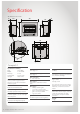
Specification All dimensions are in mm. 25 750 227 45 582 645 310 528 43 79 280 Compact 2 Specification summary Input = 9-25 MJ/h Output = 1.6-5.0 kW Efficiency = 73% Heating area = up to 78 m² Gas type = NG or LPG Inbuilt radiant/convector, glass fronted, ceramic log space heater with forced convection and natural draft flue system. Burners Ember bed and flame burner Combustion system Naturally aspirated multi port burner. Data plate Inside the appliance on the front right hand side panel.
Clearances The appliance must not be installed where curtains or other combustible materials could come into contact with the heater. In some case curtains may need restraining. The clearances listed below are minimum clearances unless otherwise stated. 80 mm Clearances The side and vertical clearances are measured from the edge of the frame. The 180 mm side clearance includes side walls.
Location The main points governing location are flueing and warm air distribution. The heater must not be installed where curtains or other combustible materials could come into contact with the appliance. In some cases curtains may need restraining. Enclosure dimensions The heater must be positioned on a flat level surface that allows free movement of the appliance. -- Masonry installations Use a slurry of sand and cement to level the base as required.
Gas and electrical connection Gas pipe sizing must consider the gas input to this appliance, as well as other gas appliances in the premises. The gas supply termination is inside the heater, and enters from the rear of the appliance. ½ ˝ BSP flared nut The length of the gas supply termination is measured from the front of the enclosure, including the thickness of any cladding material. ½ ˝ BSP male flare x ½ ˝ barrel union - elbow Vertical centre line Gas supply location 2 Gas supply location 1.
Compact 2 Flueing
Flueing options Masonry - no flexiliner Masonry - flexiliner Zero clearance- direct and offset Zero clearance - offset Flueing notes Masonry flueing Rinnai strongly recommends the use of a Rinnai flexiliner flue system. Failure to meet this criteria may result in an unsafe situation. Installation without a flexiliner flue is permissible as long as the chimney is checked for soundness and ability to achieve a good draw. If in doubt install a Rinnai flexiliner flue system.
Flueing guidelines Clearance to combustibles Minimum clearance from inner flue to combustible material must be greater than 25 mm. Flashings To top of chimney structure do not form part of the flue kit and must be specified. Flue cowl clearance To ensure products of combustion are cleared, adequate clearance for the building is required. The flue cowl should have a 500 mm clearance from any part of the building. This also applies to steeped and pitched roofs which should be clear of the ridge line as shown.
Masonry flue installations There are two types of masonry flue installations; open chimney and lined chimney. An open chimney uses the natural draft properties of a sound chimney, and an approved chimney plate and cowl to provide flueing for the heater. A lined chimney installation is used when the existing chimney condition is inadequate for an open chimney installation, and uses a Rinnai flexiliner system to provide flueing for the heater.
Compact 2 Installation
Masonry installation (without flexiliner flue) Masonry installation overview 1. Prepare site 2. Unpack heater engine 3. Prepare heater engine 4. Position heater engine 5. Connect the electrical supply 6. Insert heater into fireplace 7. Connect gas 8. Leak test 9. Secure heater 10. Complete installation 1. Prepare site Ensure the intended enclosure meets the dimension requirements, and that the gas and electrical supplies have been prepared in accordance with the information stated on page 7. 2.
Zero clearance installation Zero clearance installation overview 1. Prepare site 2. Assemble zero clearance box 3. Fit zero clearance box 4. Install flue 5. Unpack heater engine 6. Prepare heater engine 7. Fit cladding 8. Connect flue adaptor 9. Position heater engine 10. Connect electrical supply 11. Insert heater into fireplace 12. Connect flue 13. Secure flue 14. Connect gas 15. Secure heater 16. Leak test 17. Complete installation 1.
2. Assemble zero clearance box 3. Fit zero clearance box 6. Prepare heater engine 7. Fit cladding Guide rails Flue access plate K Gas/electrical access plate 8. Connect flue adaptor 13. Secure flue Flue acccess plate Flue adaptor Rail guides 15.
Completing heater installation Heater installation overview 1. Remove burner box glass 2. Unpack log set and granules 3. Install log set and granules 4. Replace burner box glass 5. Turn on electrical supply 6. Check burner pressures 7. Attach frame assembly 8. Complete installation checklist 1. Remove burner box glass Loosen, but do not remove the two retaining screws for the bottom burner box clamp.
1. Removing the burner box glass panel 3. Install log set and granules Retaining screw Bottom burner box glass clamp Retaining screw 6. Check burner pressures Front feet as pivot points 7. Attach frame assembly Test point screw Frame mounting tabs Frame assy. securing screws Gas/electrical access plate Regulator 7. Attach frame assembly 7.
Flame pattern It may take approximately two hours of operation for the logs to achieve their full flame pattern and glow. During the initial burning in period, some smoke and smell may be experienced. The appliance should run on the high setting in a well ventilated room until these dissipate. It is important to check the flame pattern during this time.
Wiring diagram (10153) TC ( +) FAN (-) OHS FAN S WITC H B L HI/ LOW (MIC R O) 1 BL 2 R R 3 W W SV W FAN S WITC H ON/OFF (T HE R MAL) + - 2 1 S PAR KE R BR BL BL E LE CTR ODE W BL BR 220~240 v 50 Hz G /Y R BL BR W G/Y 2 1 BL W 1 2 BL W IGN S WITC H (MIC R O) Red Blue Brown White Green/Yellow OHS Overheat Switch SV Solenoid Valve TC Thermocouple Compact 2 Installation Guide: 11817-A 01-12 | 19
Experience our innovation Rinnai.co.nz 0800 746 624 https://www.youtube.