
Installation guide


Compact 2 Installation Guide: 11817-A 01-12 | 7
Gas and electrical connection
Gas pipe sizing must consider the gas input to this appliance, as well as other gas appliances
in the premises. The gas supply termination is inside the heater, and enters from the rear of
the appliance.
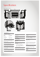
The length of the gas supply
termination is measured from the
front of the enclosure, including
the thickness of any cladding
material.
A ½ “ BSP nut and a ½ “ BSP male
flare x ½ barrel union - elbow are
provided for connection to the gas
supply. They are shipped inside the
engine attached on the gas inlet
connection of the heater.
Gas supply location
1. Mark off the location for
the vertical centre line of the
heater enclosure.
2. To the right of the vertical
centre line, mark off both the
vertical and horizontal location
for the gas supply penetration.
Purging gas supply
Foreign materials and debris
such as swarf, filings etc must
be purged from the gas supply.
Failure to do so may cause damage
to the control valve causing it to
malfunction.
Electrical connection
This appliance has a power cord
with a 3-pin plug supplied. The
power cord passes through the
slot in the lower left or right hand
side of the heater front assembly,
or from the rear panel.
Rinnai recommends that the
heater is plugged into a 230 V
10 A earthed power point. The
power point must be a minimum
of 300 mm to the side, and MUST
NOT be above the unit.
The electric isolation switch must
be accessible after the appliance
has been installed. The electrical
cord is not fire rated and should
not come into contact with the
fire.
F
R
O
N
T
O
F
EN
C
L
O
SU
R
E
(
I
n
c
l
u
d
i
n
g
C
l
a
d
d
i
n
g
)
R
E
A
R
O
F
E
N
C
L
O
S
U
R
E
4
2
3
½ ˝ BSP flared nut
Gas supply
½ ˝ BSP male flare x ½ ˝ barrel union - elbow
Gas supply location
2
= 280 mm to right of appliance centre line
3 = 43 mm from base of enclosure
4 = Gas supply to be terminated 79 mm from the
front of the enclosure
Vertical
centre line
Power cord
Rubber grommet
Electrical connection
Gas connection