SLIMFIRE 252 / " 0 ( 0 1$ 123 4 ! %05 ! %05 This appliance shall be installed in accordance with: ! " # $ % # " # &' $$ ( ) #* + # # $ # ), ' # - . All Rinnai gas products are A.G.A. certified.
Congratulations on the purchase of your Rinnai Slimfire 252 gas log flamefire. We trust you will have many years of comfort and enjoyment from your appliance. BEFORE PROCEEDING WITH THE OPERATION OR INSTALLATION OF YOUR NEW HEATER PLEASE READ THIS MANUAL THOROUGHLY AND GAIN A FULL UNDERSTANDING OF THE REQUIREMENTS, FEATURES AND OPERATION OF YOUR NEW APPLIANCE.
TABLE OF CONTENTS - OPERATION BEFORE YOU START .......................................................................................................................................... 1 INSTALLATION REQUIREMENTS ..................................................................................................................... 1 CERTIFICATION .................................................................................................................................................
BEFORE YOU START INSTALLATION REQUIREMENTS This heater must be installed by an authorised person. The installation must conform to local regulations. The installation must also comply with the instructions supplied by Rinnai. Service and removal must be carried out by an authorised person. CERTIFICATION The Rinnai Slimfire® has been certified by the Australian Gas Association. The AGA Certification Number is shown on the appliance dataplate.
INSTALLATION RECORD INSTALLERS / GAS FITTERS DETAILS Installers Name: ____________________________________________________________________ Company Name: ____________________________________________________________________ Company Address: ____________________________________________________________________ ____________________________________________________________________ ____________________________________________________________________ Company Contact Details Telephone: ________________________
SAFETY WARNING • Failure to comply with these instructions could result in a fire or explosion, which could cause serious injury, death or property damage. • Improper installation, adjustments, service or maintenance can cause serious injury, death or property damage. Such work must be performed by an authorised person. • The appliance must be installed in accordance with the local gas and electrical authority regulations. • Flue terminal must always vent directly to outdoors.
SAFETY The appliance is not intended for use by young children or infirm persons without supervision.Young children should always be supervised to ensure that they DO NOT play with the appliance. DO NOT sit or lean against the heater. DO NOT allow children or elderly persons to sleep in the warm air discharge from the heater. DO NOT post or allow children to post articles into the louvres of the heater. DO NOT cover or place articles on this heater. DO NOT place articles in front of the louvres.
SAFETY A dedicated 240V earthed 10 Amp power point MUST BE USED with this appliance. DO NOT use power boards or double adaptors to operate this appliance. The heater MUST NOT be located below a power socket-outlet. DO NOT unplug the heater while it is in operation or while the fan is still cycling. DO NOT place containers of liquid on top of the heater. Water spillage can cause extensive damage to the appliance and create an electrocution hazard. DO NOT place articles on or against this appliance.
ABOUT YOUR HEATER GENERAL DESCRIPTION Your Slimfire is a burning log effect, gas space heating appliance with natural draft combustion system, intended for use with Natural Gas and Propane. The burning log effect is achieved using two main burners with strategically placed, 'life like', imitation logs and granules. Temperature control is achieved through manual push button control. This heater has an electronic ignition. The pilot is only on when the heater is in operation.
OPERATION TO TURN YOUR HEATER ON BEFORE PROCEEDING ENSURE THE GAS AND ELECTRICITY ARE TURNED ON. NOTE You must read and understand these instructions fully before operating the heater. The push button controls are located on the front lower left hand side of the heater. Step 1. Press the right hand control (Ignition/Low) button a firmly. This operates the built-in safety device and starts the electronic spark. The front burner and pilot will ignite.
CARE AND MAINTENANCE Your heater needs very little maintenance, but the following information will help you to keep it looking good and working efficiently. DO NOT attempt to clean the heater while the appliance is hot or operating. IMPORTANT All parts of the heater can be cleaned using a soft, damp cloth. DO NOT use solvents or abrasives to clean any parts. DO NOT spray aerosols in the vicinity of the heater whilst in operation. DO NOT place articles on or against this heater.
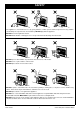
CARE AND MAINTENANCE ABNORMAL FLAME PATTERN Each Rinnai Flame Fire heater has a distinct flame pattern. The flame should look the same every time you operate your heater, after an initial warm up period of approximately 15 minutes. Abnormal flame performance and/or pattern can indicate a problem with your heater, such as blocked gas injectors, incorrectly installed / inadequate flue system or the artificial logs/burn media may have shifted from when the heater was first installed.
TABLE OF CONTENTS - INSTALLATION SAFETY ................................................................................................................................................................. 3 SPECIFICATIONS ............................................................................................................................................... 11 DIMENSIONS .......................................................................................................................................
SPECIFICATIONS Model Number RIBF2N (Natural Gas) RIBF2L (Propane) Model name Slimfire 252 Gas Log Flame Fire General description Inbuilt Radiant/Convector, glass fronted, ceramic log space heater with forced convection and natural draft flue system.
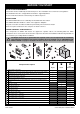
DIMENSIONS G E A H F B D C K J A B I C D E F 750mm 645mm 582mm 528mm 227mm 310mm Rinnai Australia 12 G H I J K 25mm 45mm 280mm 79mm 43mm Slimfire 252 Operation & Installation Manual
HEATER LOCATION GENERAL LOCATION INFORMATION • When positioning the heater, the main variables governing the location are Flueing and Warm Air Distribution. This heater must not be installed where curtains or other combustible materials could come into contact with it. In some cases curtains may need restraining. Refer to page 4 and page 5 for additional safety consideration.
HEATER LOCATION ENCLOSURE REQUIREMENTS Masonry Fireplace The appliance must be positioned within the fireplace on a flat level surface. If the appliance is elevated from the ground within the structure, a base must be constructed using suitable material with supporting joists capable of supporting a minimum of 1.5 times the weight of the appliance. Zero Clearance In-built installation Framework of the installation must conform to local building codes. Non-combustible materials need not be used.
HEATER GENERAL INSTALLATION GAS SUPPLY WARNING Gas pipe sizing must consider the gas input to this appliance as well as all other gas appliances in the premises. The gas meter and regulator must be specified for the total gas rate. A suitable sizing chart such as the one in AS 5601 should be used. Confirm correct gas type (see labels located on top or rear panels). Refer to local gas authority for confirmation of gas type if you are in doubt.
FLUE INSTALLATION OPTIONS WARNING The following diagrams illustrate the flue installation options that are available for the Slimfire 252 flame. Only the genuine Rinnai Flamefire (FLF) flue is certified as part of the Rinnai Slimfire 252 space heaters. Only an authorised person must install, service and remove the Rinnai Slimfire 252 space heater & flue system.
MASONRY FLUE INSTALLATION Two masonry flue installation options are available. These are Open Chimney and Lined Chimney. An ‘Open Chimney’ installation uses the natural draft properties of a sound chimney along with the addition of an approved chimney plate and cowl to provide the flueing for the heater. If there is doubt as to the soundness of the proposed chimney then a Rinnai Flexiliner FLFHA5FLEX should then be installed.
HEATER ENGINE INSTALLATION - MASONRY MASONRY INSTALLATION OVERVIEW IMPORTANT Step 1. Step 2. Step 3. Step 4. Step 5. Read this manual thoroughly and gain a full understanding of the requirements before undertaking installation. Ensure gas supply to heater is turned off for the first stages of this instruction. Step 6. Step 7. Step 8. Step 9. Step 10. Prepare Site - p.18 Unpack The Heater Engine - p.18 Preparing Heater Engine - p.18 Positioning the Heater Engine - p.19 Connect Electrical Supply - p.
HEATER ENGINE INSTALLATION - MASONRY Step 4. Positioning the Heater Engine Place the heater engine in front of the fireplace enclosure. HINT A panel from the cardboard packing carton placed on the floor underneath the heater will help prevent possible damage to flooring. Step 5. Connect Electrical Supply Plug in the 3 pin connector if electrical connections inside the fireplace. E Step 6.
HEATER ENGINE INSTALLATION - ZERO CLEARANCE ZERO CLEARANCE INSTALLATION OVERVIEW IMPORTANT Read this manual thoroughly and gain a full understanding of the requirements before undertaking installation. Ensure gas supply to heater is turned off for the first stages of this instruction. Step 1. Step 2. Step 3. Step 4. Step 5. Step 6. Step 7. Step 8. Step 9. Step 10. Step 11. Step 12. Step 13. Step 14. Step 15. Prepare Site - p.20 Assemble Zero Clearance Box - p.
HEATER ENGINE INSTALLATION - ZERO CLEARANCE Step 3. Fitting Zero Clearance Box Into Cavity J Slide zero clearance box assembly into the cavity, ensuring the gas and electricity supplies are accessible. CAUTION When preparing a cavity / frame for a zero clearance installation the total cavity depth MUST also include the thickness of the external cladding J , as the zero clearance box MUST BE installed flush with the cladding surface, failure to do this will cause misalignment of the flueing.
HEATER ENGINE INSTALLATION - ZERO CLEARANCE Step 6. Connect Transition Box to Engine Align the guide rails M with the guide plate C of the transition box assembly and slide the assembly, in until the guide plate C is fully home against the rear of the flange at the top of the heater engines main body R . C M C A R Step 7. Positioning the Heater Engine Place the heater engine in front of the zero clearance box / cavity.
COMPLETING HEATER INSTALLATION PREPARING FOR COMMISSIONING D E A D A B C B A G F H ENSURE TO LOOSEN BOTH THE LEFT AND RIGHT RETAINING SCREWS ..A .. Step 1. Removing the Burner Box Glass Loosen but do not remove the two retaining screws A for the bottom burner box glass clamp B . While supporting the burner box glass panel in place, completely unscrew and remove the two retaining screws D and the top burner box glass clamp E .
COMPLETING HEATER INSTALLATION Step 3. Installing the Log Set and Burner Granules K For clarity the drawings are displayed without showing the entire heater. NOTE DO NOT remove the burner from heater engine to install the log set. G J Use extreme care when handling the Log Set components, they are made from a very fragile high temperature material and will damage if handled roughly. Only remove the components from their packaging as required.
COMPLETING HEATER INSTALLATION COMMISSIONING THE APPLIANCE 240 VOLTS, RISK OF ELECTRICAL SHOCK! WARNING When performing the commissioning, the appliance electrical power will need to be connected. Exercise CAUTION as there is potential for electric shock from the exposed wiring and circuitry. DO NOT leave the appliance unattended when power is connected and the panels are removed. Installation and commissioning must be carried out by an Authorised person.
COMPLETING HEATER INSTALLATION ATTACHING FASCIA ASSEMBLY Step 7. Attach the Fascia to the Heater Engine Locate and remove the two 8g x 10mm fascia assembly securing screws A pre-positioned in the fascia mounting tabs B on the gas/electrical access plate C . NOTE These screws have been pre-inserted by the manufacturer to ensure correct threading of the fascia securing tabs. B A Carefully pick up fascia assembly taking care not to tilt it on it's edge as the glass may slide out of the stand off posts.
COMPLETING HEATER INSTALLATION ABNORMAL FLAME PATTERN Each Rinnai Flame Fire heater has a distinct flame pattern. The flame should look the same every time you operate your heater. Abnormal flame performance and/or pattern can indicate a problem with your heater, such as blocked gas injectors, incorrectly installed / inadequate flue system or the artificial logs/burn media may have shifted from when the heater was first installed. There are some warning signs that could indicate a problem.
WIRING DIAGRAM WIRING DIAGRAM TC FAN (+) (-) FAN SWITCH BL HI/ LOW (MICRO) 1 BL R 2 R 3 W OHS W SV W FAN SWITCH ON/OFF (THERMAL) 2 BR 1 BL + SPARKER BL ELECTRODE W BL BR 220~240 v 50 Hz BL W 2 1 G/Y 1 BL 2 W IGN SWITCH (MICRO) PN 10153 Rinnai R BL BR W G/Y RED BLUE BROWN WHITE GREEN YELLOW OHS SV TC OVER HEAT SWITCH SOLENOID VALVE THERMOCOUPLE 28 Slimfire 252 Operation & Installation Manual
CHECKLIST INSTALLATION AND COMMISSIONING CHECKLIST • Complete the Installation Check List and the Installer details below. • Instruct customer on the Slimfire 252 operation. • Ensure the customer understands the content of this manual. NOTE WARNING Advise the customer that during the initial burning period of approximately 2 hours, some smoke and odour may be experienced. During this period the heater should be operated on ‘High’ and the space being heated should be well ventilated.
NOTES Rinnai Australia 30 Slimfire 252 Operation & Installation Manual
NOTES Rinnai Australia 31 Slimfire 252 Operation & Installation Manual
NOTES Rinnai Australia 32 Slimfire 252 Operation & Installation Manual
CONTACT INFORMATION Australia Pty. Ltd. Internet: www.rinnai.com.au E-mail: enquiry@rinnai.com.au ABN 74 005 138 769 Head Office National Help Lines 10-11 Walker Street, Braeside, Victoria 3195 P.O. Box 460 Tel: (03) 9271 6625 Fax: (03) 9271 6622 Sales & Service Tel: 1300 555 545* Fax: 1300 555 655* *Cost of a local call Higher from mobile or public phones.