
Installation manual


Rinnai Australia 15 Slimfire 252 Operation & Installation Manual
HEATER GENERAL INSTALLATION
GAS SUPPLY
Installation of consumer piping
Purging Gas Supply
Foreign materials and debris such as swarf, filings, etc. MUST BE purged/removed from the gas supply, failure to
do so may cause damage to the gas control valve causing it to malfunction.
Leak Testing The Connection
Plug the end of the consumer piping gas and leak test all joints.
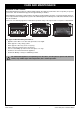
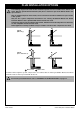
ELECTRICAL SUPPLY
If a power point is used it MUST BE 240 V, rated at 10A and MUST BE
earthed. This power point MUST NOT be located above the heater. The
heater engine is fitted with a 1.5 m power cord and three pin plug which can
exit the appliance from either the lower left or right hand side of the heater
as required.
Direct Wired Installations
Alternatively the appliance can be direct wired if the power supply is to be
concealed.
Gas pipe sizing must consider the gas input to this appliance as well as all other gas appliances
in the premises. The gas meter and regulator must be specified for the total gas rate.
A suitable sizing chart such as the one in AS 5601 should be used.
Confirm correct gas type (see labels located on top or rear panels). Refer to local gas authority for
confirmation of gas type if you are in doubt.
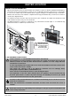
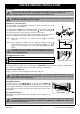
The gas supply (consumer piping), termination is inside the heater and enters
through the rear of the appliance.
A ½” BSP flared nut and a ½” BSP Male Flare x ½” Barrel Union - Elbow
are provided for connection to the consumer piping . They are shipped inside
the engine attached to on the gas inlet connection of the heater.
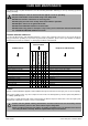
Refer to the table below and the dimensional drawings on this page and on
page 12 for appliance gas inlet location and other relevant dimensions.
Step 1. Mark off the location for the vertical centre line of the heater
enclosure.
Step 2. To the right of the vertical centre line , mark off both the vertical
and horizontal location for the gas supply penetration (consumer
piping). For measurements refer to the Gas Supply Dimension Table
below.
The length of the gas supply (consumer piping) termination is
measured from the front of the enclosure including the thickness
of any cladding material.
Gas Supply Dimension Table
280mm to right of appliance centre-line
43mm from base of enclosure
Consumer piping to be terminated 79mm from the front of enclosure
Use a soapy solution to test all gas connections. If a leak is present bubbles will form at the leak
point. When finished remove any residue with a rag. Prevent any soapy solution from coming in
contact with electrical components.
A qualified electrician will need to be consulted where a direct wired installation is required. Any
such installation must comply with the requirements of AS/NZS 5601, AS/NZS 3000 and any other
relevant local regulations.
WARNING
IMPORTANT
a
b
c
1
1
2
3
F
R
O
N
T
O
F
EN
C
L
O
SU
R
E
(
I
n
c
l
u
d
i
n
g
C
l
a
d
d
i
n
g
)
R
E
A
R
O
F
E
N
C
L
O
S
U
R
E
4
1
2
Gas supply location
3
Gas supply pressure to be 1.13 to 2.75 kPa
b
a
c
CAUTION
4
2
3
4
CAUTION
POWER CORD
RUBBER GROMMET
IMPORTANT