
Tech Bulletin

2 TB-131
2/2017
This is not an engineering schematic; it is intended only as a guide and not a replacement for professional engineering schematics.
This schematic is not intended to describe a complete system. It is up to the contractor / installer to determine the necessary
components and configuration of the particular system to be installed. The schematic does not imply compliance with local building
code requirements. It is the responsibility of the engineer or contractor to ensure that the installation is in accordance with all local
building codes. Confer with local building officials as necessary.
Note:
For Circ-Logic™
plumbing details, refer to,
“Rinnai—Hot Water System
Design Manual.”
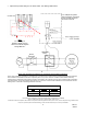
7. Adjust the dip switch settings in the water heater. See Settings table below.
Rinnai America Corporaon • 103 Internaonal Drive, Peachtree City, GA 30269
Toll-Free: 1-800-621-9419 • Phone: 678-829-1700 • www.rinnai.us
©2017 Rinnai America Corporaon. Rinnai America Corporaon connually updates materials, and as such, content is subject to change without noce.
Local, state, provincial, federal and naonal fuel gas codes must be adhered to prior to and upon installaon.
Settings for SW (bank of white switches)
Mode Switch 4 Switch 8
Economy Mode ON OFF
Comfort Mode ON ON
In a multiple unit system,
wiring should be connected
to the unit with return line
as shown to the left.
DPST-NO
Relay
Circulation Unit
PVA
Follow relay manufacturer guidelines for all electrical and grounding connections.