Outdoor Tankless Water Heater Operation and Installation Manual RL75e ................. REU-VB2528WD-US RL94e ................. REU-VB2735WD-US R98LSe ............... REU-VA3237W-US R98LSe-ASME ... REU-VA3237W-ASME FOR OUTDOOR APPLICATIONS ONLY Table of Contents ..................... 2 Consumer Safety Information ... 4 Operating Instructions............... 5 The VB series (RL75e and RL94e) are certified for installation in manufactured (mobile) homes. Register your product at www.rinnairegistration.
R R98LSe-ASME This model has been built in accordance with the requirements of the ASME Boiler and Pressure Vessel Code and has received the Certificate of Authorization from the National Board. The heat exchanger on this unit has the NB and HLW stamps. California Proposition 65 lists chemical substances known to the state to cause cancer, birth defects, death, serious illness or other reproductive harm.
Specifications Model RL75e Hot water capacity (Min - Max) * Hot water capacity (45°F rise) R98LSe 19,000 180,000 199,000 237,000 0.4 - 7.5 GPM (1.5 - 28.5 L/min) 0.4 - 9.4 GPM (1.5 - 35.5 L/min) 0.6 - 9.8 GPM (2.3 - 37 L/min) 6.6 GPM (25.1 L/min) 7.1 GPM (27.0 L/min) 8.
Consumer Safety Information Safety Definitions This is the safety alert symbol. This symbol alerts you to potential hazards that can kill or hurt you and others. DANGER Indicates an imminently hazardous situation which, if not avoided, will result in death or serious injury. WARNING Indicates a potentially hazardous situation which, if not avoided, could result in death or serious injury.
Description of Operation The Rinnai water heater is one of the most advanced water heaters available. It provides a continuous supply of hot water at a preset temperature. This appliance is a direct vent appliance where air is brought in from the outside and combustion gases are exhausted to the outside. While electricity, water, and gas supplies are connected, the Rinnai water heater produces hot water whenever a hot water tap is open. Ignition is electronic.
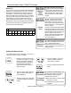
Temperature Controller MC-91-1US & MCC-91-1US Dimensions (inches): 3.5 W x 4.75 H x 0.75 D The MC-91 controller is the standard temperature controller that is supplied with the water heater. On indoor models it is integrated into the front panel. The MCC-91 controller is for commercial and hydronic applications requiring higher temperatures. When the MCC-91 controller is connected, these higher temperatures are available on all controller models in the system. Refer to the section on temperature ranges.
How to Set the Temperature Hot water can be dangerous, especially for infants or children, the elderly, or infirm. There is hot water scald potential if the thermostat is set too high. DANGER Water temperatures over 125º F (51º C) can cause severe burns or scalding resulting in death.
Temperature Controller Settings * Re-setting the Maximum Temperature (RL75 and RL94 only) Models RL75 and RL94 have a default maximum temperature of 120º F (49º C) and an option to increase the maximum temperature to 140 ºF (60 ºC). Temperature settings from 125-140 ºF (52-60 ºC) are available by setting dip switch 6 to ON in the SW1 bank of 8 dip switches. Maximum Temperature 120º F (49º C) Switch No. 140 ºF (60 ºC) Switch No.
Using the Water Smart / Bath Fill Function NOTICE Overview This function is exclusive to the BC-100V temperature controller. The bath fill function allows the consumer to fill a tub with a preset volume of water at a preset temperature. This is done by pressing the bath fill button on the BC-100V controller while no hot water is flowing and then opening only the hot water tap. The water heater will stop the hot water flow when the preset volume has been reached.
Using the Water Smart / Bath Fill Function Filling the Tub 1. Press the “Water Smart / Bath Fill” button once. The button will illuminate, and a tone will sound. ON! COLD HOT ON! HOT COLD 2. The voice prompt will announce “The hot water system is ready. Open the hot water tap.” Make sure the water volume is set. Refer to “Setting the Water Volume” on the previous page. Open the hot water tap. The “In Use” indicator will illuminate on MC-100V and BC-100V controllers. The hot water will begin to flow.
Maintenance Snow Accumulation WARNING Turn off the electrical power supply, the manual gas valve and the manual water control valve whenever servicing the unit. Repairs and maintenance should be performed by a qualified service technician. The appliance should be inspected annually by a qualified service technician. Verify proper operation after servicing. Cleaning It is imperative that control compartments, burners, and circulating air passageways of the appliance be kept clean.
Error Codes The Rinnai water heater has the ability to check its own operation continuously. If a fault occurs, an error code will flash on the display of the temperature controller. This assists with diagnosing the fault and may enable you to overcome a problem without a service call. Please identify the code displayed when inquiring about service. WARNING Some of the checks below may need to be done by a qualified service technician.
Error Codes Code Fault Remedy 14 Thermal Fuse 16 Over Temperature Warning 31 Burner Sensor Error 32 Outgoing Water Temperature Sensor Fault 33 Heat Exchanger Outgoing Temperature Sensor Fault 34 Combustion Air Temperature Sensor Fault 52 61 Modulating Solenoid Valve Signal Abnormal Combustion Fan Failure 65 Water Flow Control Fault 71 Solenoid Valve Circuit Fault Flame Sensing Device Fault Check gas type of unit and ensure it matches gas type being used.
Trouble Shooting for Common Issues I don’t have any hot water when I open the tap. White smoke comes out of the exhaust. Make sure there is gas, water, and electricity to the Rinnai water heater (power is turned on and the gas is turned on). During colder weather when the exhaust temperature is much hotter than the outside air, the exhaust fumes condense producing water vapor. When I was using the hot water, the water got cold. When I open a hot tap, I do not immediately get hot water.
Flushing the Heat Exchanger (Error Code: LC or 00) An “LC” or “00” error code indicates the unit is beginning to lime up and must be flushed. Failure to flush the appliance will cause damage to the heat exchanger. Damage caused by lime build-up is not covered by the unit’s warranty. After flushing, reset the LC fault code by turning off the power to the unit and turning the power back on. 1. 2. 3. 4. 5. 6. 7. 8. 9. 10. 11. 12. 13. KEY Disconnect electrical power to the water heater.
Installation Instructions Only properly trained and qualified installers should install this appliance. The warranty may be voided due to improper installation or installation by a non-qualified installer. Rinnai highly recommends all installers attend a product knowledge class. For information on a Rinnai Training Course or for questions on installation call 1-800-6219419. RL75e ...................... REU-VB2528WD-US RL94e ...................... REU-VB2735WD-US R98LSe....................
Clearances from Appliance to Combustibles to NonCombustibles Top of Heater 12 inches (305 mm) 2 inches (51 mm) Back of Heater 0 (zero) 0 (zero) 24 inches (610 mm) * 0 inches (0 mm) Front (Panel) Front (Exhaust) 24 inches (610 mm) 24 inches (610 mm) Sides of Heater 6 inches (152 mm) 1/8 inch (3.2 mm) Ground/ Bottom 12 inches (305 mm) 2 inches (51 mm) to top to side to front * The clearance for servicing is 24 inches in front of the water heater.
Electrical Connection The water heater must be electrically grounded in accordance with local codes or in the absence of local codes with the most recent edition of the National Electrical Code, ANSI/NFPA 70. In Canada, all electrical wiring should be in accordance with local codes and the Canadian Electrical Code, CSA C22.1 Part 1. Do not rely on the gas or water piping to ground the water heater. A screw is provided in the junction box for the grounding connection.
Gas Piping Pipe Sizing Procedure - Example The gas supply must be capable of handling the entire gas load at the location. Gas line sizing is based on gas type, the pressure drop in the system, the gas pressure supplied, and gas line type. For gas pipe sizing in the United States, refer to the National Fuel Gas Code, NFPA 54. For Canadian gas pipe sizing, refer to the Natural Gas and Propane Installation Code CAN/CSA B149.1. The below information is provided as an example.
Water Piping Isolation Valves and Pressure Relief Valve (RL75e and RL94e) The isolation valves provide the ability to isolate the water heater from the structure’s plumbing and allow quick access to flush the heat exchanger. Check with local codes to determine if a pressure and temperature relief valve is required. The included valves meet American National Standard (ANSI Z21.10.3) / Canadian Standard (CSA 4.3) and are ANSI/NSF 65 approved for potable water.
General Instructions • A manual water control valve must be placed in the water inlet connection to the Rinnai water heater before it is connected to the water line. Unions may be used on both the hot and cold water lines for future servicing and disconnection of the unit. • The piping (including soldering materials) and components connected to this appliance must be approved for use in potable water systems. • Purge the water line to remove all debris and air. Debris will damage the Rinnai water heater.
Freeze Protection Manual draining of the water heater WARNING To avoid burns, wait until the equipment cools down before draining the water. The water in the appliance will remain hot after it is turned off. If the water heater is not going to be used during a period of possible freezing weather, it is recommended that the water inside the water heater be drained. To manually drain the water: 1. Shut off cold water supply and gas supply. 2. Turn off the temperature controller.
Freeze Protection Piping Vacuum Breaker NOTICE Warranty does not cover damage due to freezing. In the event of a power failure at temperatures below freezing the water heater should be drained of all water to prevent freezing damage. Rinnai Water Heater The unit may be drained manually. However, Rinnai highly recommends that drain down solenoid valves be installed that will automatically drain the unit if power is lost.
Recommended Piping for Basic Installation Rinnai Water Heater Rinnai Equipment List QTY Rinnai Water Heaters 1 RIK-KIT (Optional) 1 (3/4" Fittings Include: 2 Unions, 2 Ball Valves, 2 Drain Valves and 1 Pressure Relief Valve.
Recommended Piping for Circulation Systems NOTE: NOTE: For residential commercial For residentialand and commercial applications, this piping arrangement applications, this piping arrangemaintains full warranty. ment maintains full warranty. Rinnai Water Heater Rinnai Equipment List For this application: Pump should be controlled by an Aquastat, Timer or Combination Aquastat and Timer.
D E L B F 26 VB Series Outdoor LS Manual B C OPERABLE FIXED CLOSED A G B B B B A J FIXED CLOSED OPERABLE I M AREA WHERE TERMINAL IS NOT PERMITTED AIR SUPPLY INLET VENT TERMINAL H K Flue Terminal Clearances (ANS Z21.10.3, CSA 4.
12 inches (30 cm) 36 inches (91 cm) * * Clearance above grade, veranda, porch, deck, or balcony Clearance to window or door that may be opened Clearance to permanently closed window Vertical clearance to ventilated soffit, located above the terminal within a horizontal distance of 2 feet (61 cm) from the center line of the terminal Clearance to unventilated soffit A B C D E 36 inches (91 cm) 36 inches (91 cm) 6 feet (1.83 m) 7 feet (2.
Additional Clearances Local codes supersede these clearances. • Avoid termination locations near a dryer vent. • Avoid termination locations near commercial cooking exhaust. 36" * (0.91 m) to ventilated or unventilated soffit or eve vent; or to a deck or porch 12" (0.
Connecting Multiple Water Heaters The EZConnect™ cable is an optional accessory that connects 2 water heaters and allows them to function as one hot water source. The MSA-2M and MSA-2S packs are optional accessories that connect 2 to 5 water heaters and allow them to function as one hot water source.
Water Heater High Altitude Installation Setting Procedure 610 - 1372 m (2001 - 4500 ft) for Canada Only / Procédure Reglage de Chaffeau á' Haute Altitude 610 - 1372 m (2001 - 4500 ft) pour Canada Seulement All settings/adjustments must be performed by a qualified Service Technician / Tous reglages/ajustements doivent être exécutés par un Technicien d'entretien qualifié. AVERTISSEMENT WARNING DO NOT adjust the other dip switches unless specifically instructed to do so.
Temperature Controller Installation Location • The controller should be out of reach of small children. • Avoid locations where the temperature controller could be splashed with liquids. • Avoid locations where the controller may become hot (near the oven or radiant heater). • Do not install in locations where it can be adjusted by the public. • Avoid locations in direct sunlight. The digital display may be difficult to read in direct sunlight.
Temperature Controller Installation Mounting the Controller Follow the procedure below to install MC-91 or MCC-91 temperature controllers. 1. Determine a suitable location for the controller. WARNING 2. Make three holes in the wall as shown. Do not attempt to connect the temperature controllers with the power on. There is 120 volt potential, next to the temperature controller connections inside the unit. 3.
Operating Instructions FOR YOUR SAFETY READ BEFORE OPERATING WARNING If you do not follow these instructions exactly, a fire or explosion may result causing property damage, personal injury or loss of life. A. This appliance does not have a pilot. It is equipped with an ignition device which automatically lights the burner. Do not try to light the burner by hand. B. BEFORE OPERATING smell all around the appliance area for gas.
Technical Data Pressure Drop Curve 100 40 90 35 80 30 70 25 60 50 20 40 15 30 10 Pressure Loss (ft head) Pressure Loss (psi) R98LSe RL94e RL75e 45 20 5 10 0 0 0 2 4 6 8 10 12 Water Flow (gpm) Outlet Flow Data 10.0 R98LSe 9.0 RL94e Water Flow (gpm) 8.0 7.0 RL75e 6.0 5.0 4.0 3.0 2.0 1.0 0.
Space Heating If the water heater is to be used for both water (potable) heating and space heating then the following apply. • The piping and components connected to the water heater shall be suitable for use with potable water. • Toxic chemicals, such as used for boiler treatment, shall not be introduced into the potable water. • The water heater shall not be connected to any heating system or components previously used with a nonpotable water heating appliance.
Dimensions RL75e, RL94e A R98LSe, R98LSe-ASME B A C D B C D E F H J DIM DESCRIPTION H J RL75e RL94e in (mm) R98LSe R98LSe-ASME in (mm) A Width 14 (355.6) 18.5 (470) B Depth 9.9 (251.1) 9.3 (230.5) C Height - Unit 22.9 (582) 23.6 (600) D Height - with brackets 25.0 (634.2) 25.2 (640) E Hot Water Outlet - from wall 3.8 (97.6) 4.5 (115) F Hot Water Outlet - from center 4.3 (110) 2.4 (61) G Cold Water Inlet - from wall 3.0 (76.6) 3.
Ladder Diagram (for RL75e and RL94e) VB Series Outdoor LS Manual 37
Ladder Diagram (for R98LSe and R98LSe-ASME) HOT NEUTRAL FROST SENSING SWITCH 3A(FUSE) ARRESTER ANTI-FROST HEATER VARISTOR VARISTOR GND RELAY 1 IG IGNITION E SWITCHING POWER SUPPLY D PG DC170V DC12V DC12.
Consumer Support Warranty Information The installer is responsible for your water heater’s correct installation. Please complete the information below to keep for your records: Purchased from: _________________________________________________________________ Address: _____________________________ Phone: _________________________________ _____________________________ Date of Purchase: __________________________________ Model No.: ________________________________________ Serial No.
Limited Warranty Continued What will Rinnai do? Rinnai will repair or replace the covered product or any part or component that is defective in materials or workmanship as set forth. Rinnai will pay reasonable labor charges associated with the repair or replacement of any such part or component. All repair parts must be genuine Rinnai parts. All repairs or replacements must be performed by an individual or servicing company that is properly trained, state qualified or licensed to do the type of repair.
State Regulations NOTICE BEFORE INSTALLATION Rinnai direct-vent appliance must be installed by a state qualified or licensed contractor and a properly trained Rinnai Installer. If you are not properly trained, you must not install this unit. IMPORTANT: In the State of Massachusetts (248 CMR 4.00 & 5.
Chauffe-eau d'extérieur sans réservoir Manuel d'installation et d'utilisation RL75e ...................... REU-VB2528WD-US RL94e ...................... REU-VB2735WD-US R98LSe .................... REU-VA3237W-US R98LSe-ASME ........ REU-VA3237W-ASME Enregistrer votre produit à www.rinnairegistration.com ou l'appel 1-866-RINNAI1 (746-6241) INSTALLATEUR : Laissez ce manuel avec l'appareil installé. CONSOMMATEUR : Conservez ce manuel comme référence ultérieure.
Instructions d'utilisation Comportements et pratiques de sécurité AVERTISSEMENT • Gardez la zone autour de l’appareil dégagée et exempte de matériaux combustibles, essence et autres vapeurs et liquides inflammables. • N’utilisez pas cet appareil s’il a été plongé dans l’eau, même partiellement. Faites inspecter l’appareil par un technicien qualifié et remplacez toute partie du système de contrôle et toute commande qui ont été plongés dans l’eau.
Plages de température avec un contrôleur de température Ce chauffe-eau va tenter de fournir de l'eau chaude à température stable malgré les variations de débit ou quand plus d'un robinet est ouvert. La chauffe-eau ne peut délivrer de l'eau qu'à une seule température de consigne à la fois.
Entretien AVERTISSEMENT Coupez l'alimentation électrique, et fermez l'arrivée de gaz et d'eau à leur vanne de coupure manuelle avant toute intervention sur l'unité. Les réparations ne doivent être effectuées que par un technicien de service qualifié. Cet appareil doit être inspecté annuellement par un technicien de service qualifié. Vérifiez le bon fonctionnement après chaque intervention.
Installation Instructions Seuls des installateurs qualifiés avec une formation adéquate peuvent installer cet appareil. La garantie peut être annulée suite à une installation incorrecte ou réalisée par un installateur non qualifié. Rinnai recommande fortement que les installateurs suivent une classe pour la connaissance des produits. Pour vous informer sur les cours de formation de Rinnai, appelez : 1-800-621-9419. RL75e ...................... REU-VB2528WD-US RL94e ......................
Écartements par rapport à l'appareil Vers le haut Jusqu'à matières combustibles Jusqu'à matières non-combustibles Dessus du chauffe-eau 12 pouces (305 mm) 2 pouces (51 mm) Arrière du chauffe-eau 0 (zero) 0 (zero) Le devant (le Panneau) 24 pouces (610 mm) * 0 pouces (0 mm) Le devant (l'Echappemen t) 24 pouces (610 mm) 24 pouces (610 mm) Côtés du chauffe-eau 6 pouces (152 mm) 1/8 pouce (3,2 mm) Par rapport au plancher/sol 12 pouces (305 mm) 2 pouces (51 mm) to top Surto leside côté Vers
Raccordement électrique Le chauffe-eau doit être électriquement relié à la terre en conformité avec les normes locales et, en leur absence, avec la plus récente édition de la norme électrique américaine, ANSI/NFPA 70. Au Canada tout câblage électrique doit être en conformité avec les normes locales et la norme électrique canadienne, CSA C22.1 Partie 1. Ne vous contentez pas de la tuyauterie d'eau ou de gaz pour raccorder la terre du chauffe-eau.
Installations à haute altitude Disposez les micro-commutateurs N° 2 et N° 3 sur les positions montrées dans le tableau qui suit en fonction de votre altitude d'installation. AVERTISSEMENT NE modifiez PAS la disposition des autres micro-commutateurs DIP sauf sur instructions spécifiques. Micro-commutateur 0-2000 ft (0-610 m) 2001-5200 ft (610-1585 m) 5201-7700 ft (1585-2347 m) 7701-10200 ft (2347-3109 m) N° 2 OFF OFF ON ON N° 3 OFF ON OFF ON N° de micro‐ Switch No.
Tuyauterie d'eau Valve à Bille / Valve de dégagement de pression (RL75e, RL94e) Les soupapes d'isolement offrent la possibilité d'isoler le chauffe-eau de la structure plomberie et de permettre un accès rapide à vider l'échangeur de chaleur. Vérifiez auprès des codes locaux pour déterminer si une soupape de pression et de température est nécessaire. Les valves inclus rencontrer American National Standard (ANSI Z21.10.3)-norme canadienne (ASC 4.3) et sont ANSI/NSF 65 approuvé pour l'eau potable.
Tuyauterie d'eau Instructions générales • Une vanne manuelle de coupure d'eau doit intercalée sur la conduite en amont sur l'arrivée d'eau au chauffe-eau Rinnai. Des raccords union peuvent s'utiliser sur les conduites d'eau froide et d'eau chaude pour faciliter les interventions ultérieures avec déconnexion de l'unité. • La tuyauterie (incluant les matériaux de soudage) et les composants connectés à cet appareil doivent être approuvés pour une utilisation sur des systèmes à eau potable.
D E L B F B C OPERABLE OUVRABLE CLOSED FIXED FERMETURE PERMANENTE A G B B DÉTAIL D'ANGLE INTÉRIEUR B B A J FIXED FERMETURE PERMANENTE CLOSED OPERABLE OUVRABLE I M Manuel – Chauffe-eau d’extérieur série VB LS K ZONE NON AUTORISÉE ENTRÉE D'ALIMENTATION EN AIR TERMINAISON DE VENTILATION H Espacements pour terminaisons de cheminée (ANS Z21.10.3, CSA 4.
* * Dégagement par rapport à fenêtre constamment fermée Dégagement vertical jusqu'à soffite ventilé situé au-dessus de la terminaison à une distance horizontale de 2' (61 cm) de l’axe de la terminaison.
Tuyauterie recommandée pour installation de base Rinnai Chauffe-eau Water Heater Rinnai Liste d'équipement Rinnai Qté Rinnai Equipment List QTY Chauffe-eau Rinnai 1 Rinnai Water Heaters 1 Kit RIK (optionnel) 1 (raccords po (19 mm) 1 RIK-KIT 3/4 (Optional) comprenant : Include: (3/4" Fittings 22unions, à boisseau Unions,2 2vannes Ball Valves, sphérique, 2 électrovannes de 2 Drain Valves and 1 Pressure Relief Valve.
Instructions d'utilisation À LIRE AVANT LA MISE EN SERVICE POUR VOTRE SÉCURITÉ AVERTISSEMENT A. B. Si vous ne suivez pas exactement ces instructions, il peut en résulter un départ d'incendie ou une explosion, causant dégâts Cet appareil ne comporte pas de veilleuse. Il est muni d’un dispositif d’allumage qui allume automatiquement le brûleur. Ne tentez pas d’allumer le brûleur manuellement. AVANT DE FAIRE FONCTIONNER, reniflez tout autour de l’appareil pour déceler une odeur de gaz.
Diagramme en escalier (RL75e, RL94e) NEUTRE PHASE FUSIBLE 3 A (intérieur) FUSIBLE 5 A (extérieur) CONTACT DE DÉTECTION DE GEL ANTI-FOUDRE ANTI-FOUDRE VARISTOR VARISTOR TERRE ALLUMAGE RELAIS 1 ALIMENTATION À DÉCOUPAGE 170 V CC 12 V CC 12,6 V 40 V CC 5 V CC DÉTECTEUR D'ÉCOULEMENT ÉLECTROVANNE À MODULATION CIRCUIT DÉTECTEUR CIRCUIT D'ALIMENTATION D'ÉLECTROVANNE À MODULATION DISPOSITIF DE CONTRÔLE D'ÉCOULEMENT CIRCUIT DISPOSITIF DE CONTRÔLE VEBTILATEUR DE COMBUS- CIRCUIT DE CONTRÔLE D'ÉCOULE
Diagramme en escalier (R98LSe, R98LSeASME) PHASE HOT FUSIBLE 3 A (intérieur) FUSIBLE 5A 3A(FUSE) (extérieur) NEUTRE NEUTRAL CONTACT DE FROST SENSING DÉTECTION SWITCH DE GEL ANTI-FOUDRE ARRESTER ANTI-FOUDRE ANTI-FROST HEATER VARISTOR VARISTOR VARISTOR VARISTOR GND TERRE RELAIS RELAY 11 IG ALLUMAGE IGNITION E ALIMENTATION À SWITCHING DÉCOUPAGE POWER SUPPLY D PG 170 V CC DC170V 12 V CC DC12V 12,6 V DC12.
Support à la clientèle Informations sur la garantie L'installateur est responsable de l'installation correcte de votre chauffe-eau.
Garantie limitée Que fait Rinnai pour exercer la garantie ? Rinnai va réparer ou remplacer le produit, ou toute partie ou tout composant défectueux pour cause de matériaux ou de main d'œuvre, dans les conditions définies plus loin. Rinnai remboursera des charges de main d'œuvre raisonnables associées avec la réparation ou le remplacement de toute pièce ou tout composant. Toutes les pièces utilisées pour la réparation doivent être des pièces Rinnai d'origine.
VB2528W VB2735W VA3237W U287-1932(00) Printed in Japan 060 00012 30660 6