
System Design Drawings

Solar Storage Tank
AB 11.16.2018
RS 12.15.2018
This is not an engineering drawing; it is intended only as a guide and not
as a replacement for professional engineering project drawings. This
drawing is not intended to describe a complete system. It is up to the
contractor or engineer to determine the necessary components and
configuration of the particular system to be installed. The drawing does
not imply compliance with local building code requirements. It is the
responsibility of the engineer or contractor to ensure that the installation is
in accordance with all local building codes. Confer with local building
officials before installation.
THIRD ANGLE PROJECTION
D
C
B
A
A
B
C
D
1
2
3
4
5
6
7
8
8
7
6 5
4
3
2
1
PROHIBITED.
WH2-S-2
MACHINED X.XXX =
SHEET 1 OF 1
0.005
RINNAI AMERICA CORPORATION
Systems Design Manual
103 INTERNATIONAL DRIVE
PEACHTREE CITY, GA 30269
12.15.2018
1-800-621-9419
SH
Angle =
UNLESS OTHERWISE SPECIFIED:
INTERPRET GEOMETRIC
SCALE: NTS
DO NOT SCALE DRAWING
WEIGHT:
0.010
TOLERANCING PER:
MATERIAL
FINISH
DRAWN
CHECKED
ENG APPR.
COMMENTS:
DATENAME
TITLE:
SIZE
B
DWG. NO.
REV
TOLERANCES:
Sheet Metal X.XX = 0.030
X.XXX = 0.010
Fraction = 1/32
Angle = 1.0
THE INFORMATION CONTAINED IN
THIS DRAWING IS THE SOLE
PROPERTY OF RINNAI AMERICA. ANY
REPRODUCTIONIN PART OR AS A
WHOLE WITHOUT THE WRITTEN
PERMISSION OF RINNAI AMERICA IS
PROPRIETARY AND CONFIDENTIAL
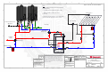
Note:
1. Ensure TMV1 check valves are removed. (This will
be diverter valve.)
2. Set TMV1 20F below Rinnai temperature setting.
3. TMV2 should be set to desired domestic
temperature.
4. For lowest activation flow rate, ensure water heaters
are connected with appropriate cascade controls.
Condensate Drain Line As
C
old Water Supply
Collector Sensor
Supply
Hot Water
Appropriate
Gas Supply
Tank Sensor
Solar Controller
Thermostatic
Mixing Valve 2
Two Unit Solar Backup Option 2
Thermostatic
Mixing Valve 1
Rinnai Tankless
Applies to HE, HE+, SE, and Sensei Models