Installation & Servicing Instructions High efficiency condensing gas boiler Q85SN/Q130SN/Q175SN/Q205SN/Q175CN Q85SP/Q130SP/Q175SP/Q205SP/Q175CP CAUTION! Read this manual thoroughly before installing, servicing, putting into operation or using this boiler and vent system. WARNING! Improper installation, adjustment, alteration, service or maintenance can cause property damage, personal injury or loss of life. Refer to this manual.
Contents of instructions These installation instructions contain important information for the safe installation, start-up and maintanance of boilers with capacities 85,000 through 205,000 BTU/hr. These installation instructions are intended for professional installers, who have the necessary knowledge and are approved for working on heating and gas systems.
1 Safety and general instructions 1.1 Designated use 1.2 Hazard definitions 1.3 Symbol definitions 1.4 The following instructions must be followed 1.5 Follow these instructions for the space heating water 1.6 Tools, materials and additional equipment 1.7 Relevant Installation, Service and User manuals 1.8 Disposal 2 Regulations and guidelines 3 Description of the boiler 4 Packaging and transportation 4.1 Scope of delivery 4.2 Transportation 5 Installation 5.1 Requirements for the installation room 5.
1 Safety and general instructions Please observe these instructions in the interest of your own safety. 1.1 Designated use The boiler is designed for heating water for a central heating system and, if applicable, generating domestic hot water. The boiler is delivered with a burner controller (MCBA) pre-installed.The boiler can be fitted with a modulating outdoor reset sensor ARV12 (included with the boiler) or an On/Off thermostat or relay panel end switch (accessories). 1.
1.4 The following instructions must be followed - - - The boiler must only be used for its designated purpose, as described in the Installation Instructions. Each unit is fitted with a data plate. Consult the details on this plate to verify whether the boiler is compliant with its intended location, e.g.: gas type, power source and venting classification. Only use the boiler with the accessories and spare parts listed.
1.5 Follow these instructions for the space heating water Unsuitable heating system water can cause the formation of scale or sludge, which affects system efficiency. It can also cause corrosion and reduce life of the heat exchanger. – You must follow Rinnai guidelines for boiler water quality. – Thoroughly flush the system prior to filling. – Follow the Rinnai cleaning instructions. – Never use water that has been treated by a salt bedding exchangers, reverse osmosis, D.I.
2 Regulations and guidelines The installation must comply to the requirements of the authority having jurisdiction or, in the absence of such requirements, to the latest edition of the National Fuel Gas Code, ANSI Z223.1/NFPA 54. In Canada, installation must be in accordance with the requirements of CAN/CSA B149.1, Natural Gas and Propane Installation Code.
For direct-vent boilers mechanical-vent heating boilers or domestic hot water equipment where the bottom of the vent terminal and the intake is installed higher than four feet above grade the following requirements must comply: 1) If not present on each floor level where there are bedrooms, a carbon monoxide detector and alarm must be placed in a living area outside the bedrooms. The carbon monoxide detector and alarm must comply with NFPA 720 (2005 Edition).
4 Packaging and transportation 4.1 Scope of delivery The boiler is supplied ready for use. • Please check if the packaging is intact. • Check if all the items listed are included in the delivery.
5 Installation 5.1 Requirements for the installation room ! DANGER - - Installation & Servicing Instructions Rinnai Q-Series - 10 The room where the boiler will be placed must always be frost free. Do not store or use gasoline or other flammable vapors and liquids in the vicinity of this or any other appliance. Never use or store any chlorinated detergents or halogenated hydrocarbons (e.g. in spraycans, solvents and detergents, paints, adhesives) in proximity of the boiler.
5.2 Fitting the boiler i NOTICE i NOTICE - Remove the packaging materials. - Do not tear the packaging. Take notice of the presence of the mounting template at the inside of the carton wrapper. Lay the boiler on its back during unpacking. When unpacking, the casing can be removed from the boiler. This part can be kept apart during installation. It must be placed on the boiler and fixed with the screw behind the door before the boiler is started up.
5.3 Dimensions F D D E V V 0.4" 10 A wall 2" 50 wall wall C B B Min.
Connection for combustion air supply and vent system f r c g f r g c f r c e k boiler connections figure 2 Boiler type Vent system / Combustion air supply Gas pipe - g Supply pipe - f Return pipe - r Condensate pipe - c Expansion pipe - e Cold water pipe - k Hot water pipe - w connection diameters w Solo Q85SN/Q85SP Q175SN/Q175SP Q130SN/Q130SP Q205SN/Q205SP 80/125mm 3/4"M-NPT 1.1"x 1"M-NPT / 28mm 1.1"x 1"M-NPT / 28mm 0.95" / 24mm 80/125mm 3/4"M-NPT 1.4"x 1¼"M-NPT / 35mm 1.
5.3.1 Plumbing Kits Rinnai supplies with each type of boiler a Plumbing kit. Find below the dimensions. See chapter 6.1 for additional information. (REF. 5.29) (REF. 15.82) Plumbing Kit 2 100mm 3.937 Suitable for: Q85SN / Q85SP Q130SN / Q130SP (REF. 19.64) 1 1/4” 1 1/4” 9.00 Plumbing kit 2 fig.3 (REF. 19.07) Plumbing Kit 3 Suitable for: Q175SN / Q175SP Q175CN / Q175CP Q205SN / Q205SP (REF. 5.42) 260mm 10.236 14 (REF. 20.
5.3.2 Clearences from the boiler ceiling Min. 10" / 250mm 2" 50 24" 600 2" 50 wall 15.
5.4 Technical specifications Units Combi Q175CN Q175CP Q85SN Q85SP Q130SN Q130SP Q175SN Q175SP Q205SN Q205SP BTU/hr 175,000 85,000 130,000 175,000 205,000 Qn Output non-condensing CH BTU/hr 157,000 77,000 117,000 157,000 184,000 Qn Output EN677 eff. CH BTU/hr 172,400 84,000 127,600 172,400 202,200 Qn Output AFUE CH BTU/hr 167,500 82,000 124,900 167,500 196,200 Efficiency at 36/30ºC (96.8/86ºF) part load, Hs, EN677 CH % 98.5 98.8 98.2 98.5 98.
6 Connecting the boiler The boiler has the following connection pipes; - The central heating circuit pipes. These must be connected to the Plumbing Kit by means of adapter fittings. See further chapter 6.1; - The gas supply pipe. It is provided with a 3/4" male thread into which the tail piece of the gas valve can be screwed. See further chapter 6.4; - The condensation drain pipe. It consists of an oval 1" (24 mm) plastic pipe. The drain pipe can be connected to this by means of an open connection.
6.1.1 Plumbing Kit installation Rinnai supplies specific Plumbing Kits with each boiler type, which must be fitted directly underneath the boiler on the supply and return pipe. Use of the Rinnai boiler without the plumbing kit will result in the void of warranty. i NOTICE i NOTICE To protect the entire heating system we recommend installing a dirt particle trap in the return circuit. When the boiler is installed to an existing heating system this trap is required.
The boiler has a self-adjusting and self-protecting control system for the load and the pump capacity. By this means the temperature difference between the supply and return water is checked. NOTICE The boiler is designed to be used on pressurized heating systems only.
6.1.2 Safety valve An ASME 30 psi pressure relief valve is installed on the plumbing kit included with the boiler. 6.1.3 i NOTICE Low water cut off The Rinnai Q boiler has a factory installed pressure switch type Low Water Cut Off (LWCO). Check your local codes to see if a Low Water Cut Off is required (LWCO) and if this device conforms to local code. See the Rinnai Boiler Applications Manual for further information. The Low water cut off is not serviceable. 6.
6.4 Gas connection ! DANGER Only work on gas lines if you are licensed for such work. If these instructions are not followed exactly, a fire or explosion may result causing property damage, personal injury or death. ! WARNING Rinnai wall mounted boilers are built to run on Natural Gas or Propane Gas. The gas type the boiler is suitable for is indicated on the packaging and on the boiler by a blue label with Natural Gas or a green label with Propane Gas and on the identification plate on the boiler.
6.4.2 i NOTICE Gas connection with propane gas The gas supply connection must comply with local regulations or, if such regulations do not exist, with the National Fuel Gas Code, ANSI Z 223.1. For Canada, the gas connection must comply with local regulations or, if such regulations do not exist, with the CAN/CSA B149.1, Natural Gas and Propane Installation Code. Pipe sizing for propane gas - Contact gas supplier to size pipes, tanks, and 100% lockup gas pressure regulator.
6.5 Hot water supply (Combi boiler Q175CN/Q175CP) Connection of the drinking water installation should be performed according to the national secondary drinking water regulations. ! DANGER Do NOT use toxic chemicals, such as are used for boiler treatment in potable water heating systems used for space heating. The sanitary water pipes can be connected to the installation by use of adapter fittings.
6.7 Vent system and air supply system Provisions for combustion and ventilation air must be made in accordance with section, Air for Combustion and Ventilation of the National Flue Gas Code, ANSI Z223.1, or Sections 7.2, 7.3 of 7.4 of CAN/CGA B149.1, Installation Codes, or applicable provisions of the local building codes. - i NOTICE 6.7.1 Do not store chemicals near the boiler or in rooms where the air is being supplied to the boiler. See the list on page 10.
6.7.
6.7.
6.7.3 Installation of the vent system i NOTICE Consult local and state codes pertaining to special building code and fire department requirements. Adhere to national code requirements. i NOTICE Follow the listed maximum length of vent systems, which are boiler output dependent. The maximum permissible lengths are listed in table 9, chapter 6.7.6. Decide how to install the exhaust and air intake system. You can choose among: - Concentric system The concentric connection is provided standard initially.
6.7.4 Recommended vent/air intake terminal position Terminals should be positioned as to avoid products of combustion entering openings into buildings or other vents. Maintain 12” of clearance above the highest anticipated snow level or grade or, whichever is greater. Please refer to your local codes for the snow level in your area.
The termination shall be at least 4 feet (1,220 mm) for the US and 6 feet (1,830 mm) for Canada distance from electric meters, gas meters, regulators and relief equipment. (for room air application only) i NOTICE ! CAUTION ! CAUTION The whole route of the vent system must be installed upwards, never downwards, completely nor partly.
6.7.5 ! DANGER Dimensioning of the exhaust and air intake duct The wall mounted boiler must be vented and supplied with combustion and ventilation air as described in this section. Ensure the vent and air piping and the combustion air supply comply with these instructions regarding vent system, air system, and combustion air quality. Inspect finished vent and air piping thoroughly to ensure all are airtight and comply with the instructions provided and with all requirements of applicable codes.
6.7.6 Combustion air and vent piping lengths. In the table below you find the maximum equivalent pipe length of the vent/air system based on 3" diameter. These lengths are for single pipe (room air), twin pipe, and concentric venting systems.
6.7.7 Calculation of compensation factor The compensation factor eliminates or reduces the natural effect of derate of maximum input caused by the resistance of the vent system and/or the impact of the altitude. 1. Determine the Compensation Factor Vent System CF(V) in the table below. Eq. length (ft) Q85 min 00 11 10 21 20 31 30 41 40 61 60 81 80 max 10 20 30 40 60 80 100 0 0 0 1 2 3 4 Boiler type Q130 Q175 CF (V) 0 0 0 2 2 4 4 6 6 10 8 15 10 n.a.
6.7.8 Room Air System (indoor combustion air) When using indoor air, Rinnai strongly recommends the use of an indoor air filter, P/N This water heater requires adequate combustion air for ventilation and dilution of flue gases. Failure to provide adequate combustion air can result in unit failure, fire, explosion, serious bodily injury or death. Use the following methods to ensure adequate combustion air is available for correct and safe operation of this water heater.
6.7.8 Room Air System (indoor combustion air) Confined Space: (Small Room, Closet, Alcove, Utility Room, Etc.) A confined space is defined in the NFPA #54 as "a space whose volume is less than 50 cubic feet per 1000 Btu/hr (4.8 m3 per kW per hour) of the aggregate input rating of all appliances installed in that space." A confined space must have two combustion air openings.
6.7.8 Room Air System (indoor combustion air) Using Indoor Air For Combustion When using air from other room(s) in the building, the total volume of the room(s) must be of adequate volume (Greater than 50 cubic feet per 1000 Btu/hr). Each Combustion air opening must have at least one square inch of free area for each 1000 Btuh, but not less than 100 square inches each.
7 ! External domestic hot water tanks WARNING Note the local codes for requirements for connecting an external hot water cylinder to the boiler. The installation must comply to these codes. Depending on the domestic hot water requirements and comfort preferences various external hot water tanks can be connected to the boiler. Connecting an external hot water tank to the Q175C is NOT possible. Connecting an external hot water tank to the Q-Series solo boilers can be done in 2 ways: 1.
8 Electrical connections The electrical connections to the boiler must be made in accordance with all applicable local codes and the latest revision of the National Electrical Code, ANSI/NFPA-70. Installations should also conform with CSA C22.1 Canadian Electrical Code Part 1 if installed in Canada.
electrical diagram 2 Amp. max. Installation & Servicing Instructions Rinnai Q-Series X7 ! E-Prom 120V T 220°F 120V 120V figure 17 CAUTION Label all wires prior to diconnection when servicing or replacing controls.
Installation & Servicing Instructions Rinnai Q-Series electrical ladder diagram figure 17a
9 Boiler controls The boiler is provided with a fully automatic microprocessor control, called CMS Control Management System. This control simplifies operation by undertaking all major control functions. Initially when power to the unit is switched on it will remain on standby. There is no indication LED on, until one of the program buttons is pressed. The control panel display will show the relevant state. When the installation is empty the display will show FILL.
9.1 Explanation of the function buttons 1 2 3 7 4 5 6 8 Boiler control panel i NOTICE figure 18 Only qualified personel who are trained for servicing these boilers are permitted to make alterations in the controller to calibrate the boiler to the installation. 1. Display. See previous page for further information. 2. ON-OFF Switch This switch turns the power supply to the boiler on or off. ! i CAUTION Only turn the boiler off using this switch, when the burner is off. 3.
10 Starting up: Filling and de-aerating the boiler and installation ! CAUTION i NOTICE i NOTICE ! WARNING CAUTION Observe the following rules of safety: - All work on the unit must take place in a dry environment. - Rinnai units may never be in operation without their housing, except in connection with maintenance or adjustments (see Chapter 13 and 14). - Never allow electrical or electronic components to come into contact with water.
Freeze protection Freeze protection for new or existing systems must use glycol that is specially formulated for this purpose. This includes inhibitors, which prevent the glycol from attacking the metallic components. This should be for multi-metallic components. Make certain to check that the system fluid is correct for the glycol concentration and inhibitor level. The system should be tested at least once a year and as recommended by the producer of the glycol solution.
i NOTICE It can take a while before all air has disappeared from a filled installation. Especially in the first week noises may be heard which indicate the presence of air. The automatic air vent in the boiler will remove the air, which means the water pressure can reduce during this period and therefore topping off with water will have to be done.
FOR YOUR SAFETY READ BEFORE OPERATING WARNING: If you do not follow these instructions exactly, a fire or explosion may result causing property damage, personal injury or loss of life. A. This appliance does not have a pilot. It is equipped with an ignition device which automatically lights the burner. Do NOT try to light the burner by hand. B. BEFORE OPERATING smell all around the appliance area for gas. Be sure to smell next to the floor because some gas is heavier than air and will settle on the floor.
11 Adjustments When the boiler is installed it is ready for use. All adjustments of the boiler control are already pre-programmed for a heating system with radiators/convectors with a supply temperature of 185°F. The adjustments are described in the Parameter chapter on page 44. In certain cases parameters have to be altered in case of : - Lower supply temperature - High altitude/long vent length Read through the Parameter chapter to adjust the boiler to its installation. Contact Rinnai in case of doubt.
Parameter-Mode 1 21 2* . . 176ºF (80ºC) 01186°F 01 3 4* max. 00 5* 6* 7* 10* 11* 14 15* 2.3 1.4 14°F 0°F 0°F 10°F/min. 00 23 27 31 36 26°F 32°F 146°F (154°F) 01 43 49 73 max. 100% 0 89 00 90 Description . Range . 68 -- 186°F 68 176 F maximum supply temperature CH maximum temperature CH type of CHsupply installati on: type of CH installation: radiators; air heating; convectors: 00 DO NOT USE air heating; Tradiators; max. supply 176ºFconvectors: (80ºC); K factor heating curve 2.
Service Mode Service-Mode SERV SERV VALUE Value 1 2 3 4 OFF OFF OFF OFF DESCRIPTION Description boiler in operation with burner function on fan adjustable and burner off pump adjustable with burner on showroom position ON = active and OFF = non active RANGE Range OFF - max. OFF - max. OFF - max. ON - OFF . . . . Error Mode Error-Mode ERROR ERRO VALUE Value Err.L - Err.
11.2 Activating factory settings (green button function) To activate the factory settings again please follow the next procedure (Note: all altered adjustments will be set back to the original factory settings): - Select, when necessary, the technical read out; - Select with the MODE-button chapter PARA; - Press the STORE-button. The word "Copy" will appear and factory settings are active again. 12 Isolating the boiler Some situations require turning the entire boiler off.
13 i Commissioning Work on the boiler must be carried out by a competent person, using correctly calibrated instruments with current test certification. These installation instructions are intended for professional installers, who have the necessary knowledge and are approved for working on heating and gas systems. NOTICE Before the boiler is fired, ensure that the boiler and the system are well de-aerated and free of air. Purge the gas line between the gas meter and the boiler.
13.1 Testing for gas leaks Prior to start-up of the boiler you must check the external tightness of the gas supply valve and confirm this in the start-up report. ! WARNING ! DANGER - Cover endangered positions before leak testing. Do not spray the leak testing agent onto cables, plugs, electrical connection lines or electronic circuit boards. Do not allow it to drip onto them either. Leaks may be caused to pipes and screw connections during commissioning and maintenance activities.
13.3 Checking for contamination i NOTICE In order to be able to check the boiler for contamination in the following running years it is advisable to measure the maximum air displacement in the boiler when putting the boiler into operation. This value can be different with each type of boiler. In order to be able to measure this value follow the next procedure: - Press the MODE-button for 5 seconds.
13.4 Checking of the zero pressure control i NOTICE The zero pressure control is set at the factory. To measure this value you need a difference pressure gauge with a range of +0,2 to -0,8 mbar (+0.08 to -0.001” W.C.). Follow the next procedure: - Press the MODE-button for 5 seconds.
13.5 Checking the O2 i The O2 percentage is factory-set. This has to be checked at commissioning, maintance and faults. NOTICE This can be checked by means of the following procedure: - Remove the black cover of the gas valve by unscrewing the sealed screw. - i checkpoint CO2 figure 21 Put the boiler into operation and take care that it can deliver its heat; Tip: If there is no demand for heat on CH, turn the hot water tap completely open and measure the O2. - Press the MODE-button for 5 seconds.
13.6 Measuring the ionization current Switch off the system using the Central Heating button and the DHW button - Disconnect the plug and the socket connection on the probe and connect the measuring device in series. See figure 23. Select the µA direct current range on the measuring device. The measuring device must have a resolution of at least 1 µA. - Switch on the sytem using the Central Heating button and the DHW button. - Press the MODE-button for 5 seconds.
2 1 - Install the metal casing on the boiler; - lock the casing by using the screw behind the door. See figure 25. 3 Installing casing 14 i figure 25 Maintenance Maintenance or changes to the boiler may only be carried out by a qualified technician. NOTICE 14.1 Periodic examination of venting systems and boiler i The inspection of the boiler and venting system should be done every 2 years and full maintenance every 4 years or 4000 hours of operation, whichever occurs first.
14.2.1 Visual inspection for general signs of corrosion - 14.2.2 Check all gas and water pipes for signs of corrosion. Replace any pipes that are corroded. Measuring the ionization current See subsection 13.6 “Measuring the ionization current”. 14.2.3 Measuring the inlet gas pressure See subsection 6.4.1 and .2 “Gas connection with natural gas" and "Gas connection with propane”. 14.2.4 Checking and adjusting the gas/air ratio See subsection 13.4 “Checking of the zero pressure control”. 14.2.
14.3 Maintenance activities i NOTICE 2 9 1 4 The fan unit and burner cassette (figure 28 to 30) (2 and 4 year maintenance) - remove the electrical connection plug from the gas valve (1) and fan motor (2); - loosen the nut (3) of the gas pipe under the gas valve; - replace the gasket with a new one; - loosen the front cross head screw (4) of the black plastic silencer; - after this turn the two clamping rods (9 and 10) ¼ turn and remove them by pulling them forward.
- remove and replace the gasket; Refitting of the components is done in reverse order. 9 10 8 7 Siphon figure 31 13 14 12 11 Condensate tray ! Condensate trap and condensate tray (figure 31-33) (2 and 4 year maintenance) Step 1: Condensate trap - first remove the condensation cup (7); Check this for impurities. If there is not a lot of impurities it is not necessary to clean the condensate tray (Go to Step 3).
Visual inspection of the flame The burner must flame evenly over the entire surface when operating correctly. The flame must burn with a clear, blue, stable flame. Check the flame through the inspection glass in the ignition probe (fig. 34). The flame pattern should be as shown in the figures below.
15 Parts of the boiler 4 2 1 3 7 5 16 15 6 17 8 T1 P1 T2 T3 F 18 R C 9 E K 10 11 12 13 W 14 ATAG Q 1 2 3 4 5 6 7 8 figure 34 heat exchanger ignition unit fan unit air inlet damper gas valve automatic de-aerator ceramic burner cassette DHW tank (Q175C) 9 10 11 12 13 14 operating panel Control Tower (CMS) water filter return CH three-way valve (Q175C) circulation pump thermostatic mixing valve (Q175C) 15 exhaust 16 combustion air supply 17 air box 18 data plate T1 flow sensor T2
16 Blocks and Errors 16.1 Error indication (short reference) A detected error is indicated on the display by means of blocking or error messages. A distinction should be made between these two messages due to the fact that blocking can be of a temporary nature, however, error messages are fixed lockings. The control will try its utmost to prevent locking and will temporarily switch off the unit by blocking it. Hereunder is a list of some messages. Blocks with a number in the last 2 positions.
The following pages describes more detailed follow up instructions for solving blockings, errors and practical circumstances. These instructions are only for by Rinnai trained installers and technicians. NOTICE 16.1 Blocks An error, which has been detected, is indicated on the display by a block message. Blocks can be temporary in nature. The controller will do everything possible to prevent a system lock and temporarily switching off the boiler as a result of a block.
16.1.2 Block 11 maximum average DT of supply and return sensor for central heating is repeatedly exceeded. Operation is normally possible for the hot water supply during the block. The pump continues to operate at minimum capacity during the block.
16.1.3 Block 12 maximum average DT of supply and return sensor for hot water is repeatedly exceeded. Operation is normally possible for the central heating installation during the block. The pump continues to operate at minimum capacity during the block.
16.1.5 Block 67 a temperature difference has been detected between the supply and return sensor whilst the burner is not in operation. After the average DT has disappeared, the block will disappear.
16.1.6 Block 85 no water flow can be detected through the controller. De-aeration cycle is started. When water flow is detected during this cycle, the de-aeration cycle is terminated and the burner is released. check the boiler pump check the installation for the presence of air; If there is a secondary pomp installed and it is not hydraulicly seperated could cause pressure differences. 16.1.
16.2 Errors A detected error is indicated on the display by an Error message. Error messages are permanent locks which can only be removed by pressing the reset key. The controller will make every possible attempt to prevent the lock. Below is a summary of the Errors. Error 16.2.1 with one figure on the last 2 characters. Error 00 incorrect flame formation.
Error 01 24 Volt short-circuit disconnect voltage from the boiler and check the fuse F2 as a result of a 24 Volt short-circuit inside or outside the boiler the fuse F2 will have blown. This fuse is placed in the control unit and can be seen after the black covering cap is removed. check the 24 Volt connection remove all plugs with 24 Volt connections such as: fan, pump, any three-port valve and 24 Volt plug to the connecting block.
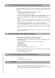
16.2.3 Error 02 no flame formation check the data in Error mode boiler data during error no temperature difference between supply (3) and return (4) 1 error 2 operational status 3 supply temp. 4 return temp.
16.2.4 Error 03 control unit error software error control unit replace the control unit. The controller will automatically load the program into the new control unit. Error 04 the controller has detected a program error reset the boiler the boiler automatically indicates this message if during an error read-out the voltage to the boiler is removed. After the voltage has once again returned, if the error causing the interference is no longer present, this message is given.
16.2.6 Error 05 control unit error check the ribbon cable between the control unit and the display incorrect data will be detected in case of a poor connection between the control unit and the display. If necessary, replace the ribbon cable between these two components. the error persists after reset software error control unit. Installation & Servicing Instructions Rinnai Q-Series replace the control unit. The controller will automatically load the program into the new control unit.
Error 07 control unit error software error control unit. check the gas valve replace the control unit. The controller will automatically load the program into the new control unit. Installation & Servicing Instructions Rinnai Q-Series 16.2.
16.2.8 Error 11 control unit error check the interface and the ribbon cable between the control unit and the display incorrect data will be detected in case of a poor connection between the control unit and the display or if the interface is incorrectly positioned. If necessary, replace the ribbon cable between these two components. the error persists after reset software error control unit Installation & Servicing Instructions Rinnai Q-Series replace the control unit.
Error 12 short-circuit 24 Volt remove the voltage from the boiler and check fuse F2 due to the 24 volt short-circuit inside or outside the boiler, fuse F2 has blown. This fuse is positioned in the control unit and can be seen when the black covering lid has been removed.
16.2.10 Error 13 control unit error software error control unit Installation & Servicing Instructions Rinnai Q-Series replace the control unit. The controller will automatically load the program into the new control unit.
Temp °F -4 -0.4 3.2 6.8 10.4 14 17.6 21.2 24.8 28.4 32 35.6 39.2 42.8 46.4 50 53.6 57.2 60.8 64.4 68 71.6 75.2 78.8 82.4 86 89.6 93.2 96.8 100.
16.2.12 Installation & Servicing Instructions Rinnai Q-Series Temp °F 78 -4 -0.4 3.2 6.8 10.4 14 17.6 21.2 24.8 28.4 32 35.6 39.2 42.8 46.4 50 53.6 57.2 60.8 64.4 68 71.6 75.2 78.8 82.4 86 89.6 93.2 96.8 100.
Temp °F -4 -0.4 3.2 6.8 10.4 14 17.6 21.2 24.8 28.4 32 35.6 39.2 42.8 46.4 50 53.6 57.2 60.8 64.4 68 71.6 75.2 78.8 82.4 86 89.6 93.2 96.8 100.
16.2.
Error 31 internal shut down of supply sensor T1 check the data in Error mode boiler data during error 1 error 2 operational status 3 supply temp. 4 return temp.
16.2.16 Error 32 shut down of return sensor T2 check the data in Error mode boiler data during error 1 error 2 operational status 3 supply temp. 4 return temp.
Error 36 contact for supply sensor T1 open check the data in Error mode boiler data during error 1 error 2 operational status 3 supplytemp. 4 return temp. 5 kW burner 6 % pump check the wiring 1 = 36 2 = 00 3 = -22 4 = xx* 5 = 00** 6 = xx* * = variable value **= x3415=BTU/hr check the wiring for the sensor the wiring is OK but the error is repeated remove the plug from the flow sensor as a result of which Error 31 occurs replace the sensor Installation & Servicing Instructions Rinnai Q-Series 16.
16.2.18 Error 37 contact for return sensor T2 open check the data in Error mode boiler data during error 1 2 3 4 5 6 error operational status supply temp. return temp.
16.2.19 Error 41 control unit error software error control unit replace the control unit. The controller will automatically load the program into the new control unit. Error 42 control unit error software error control unit replace the control unit. The controller will automatically load the program into the new control unit. Installation & Servicing Instructions Rinnai Q-Series 16.2.
16.2.21 Error 68 no software present control unit and display don't have a programm Installation & Servicing Instructions Rinnai Q-Series there are a new display and a new control unit installed at the same time. Exchange the parts and the loading will start automatically and appears on the display.
17 Other errors 17.
17.2 Hot water but no central heating hot water but no central heating -Key of the central heating program is not switched on switch on central heating program room thermostat (on/ off) is not giving any signal to the boiler check room thermostat RS100 with outdoor sensor (Room sensor-On) outdoor temperature is higher than 70°F, depending upon the Eco-temperature set (70°F is the default).
17.
17.4 Insufficient quantity of hot water insufficient quantity of hot water hot and cold water connection to the boiler mixed up check left = cold, right = hot incorrect flow reducing valve check for the type and for contamination, if necessary replace (Combi) and/or clean.
17.5 Temperature drop of the DHW (Combi) Temperature drop of the DHW (Combi) flow reducing valve check flow reducing valve for the correct type in accordance with the installation instructions thermostatic mixing valve incorrectly set adjust (by measuring the temperature) DHW power for the boiler is set too low check PARA chapter Step No.
17.5.1 Temperature drop of the Solo with the external DHW tank temperature drop of the Solo hot water with the DHW tank synchronising valve check the setting in accordance with the illustrated DHW tank installation instructions thermostatic mixing valve incorrectly set adjust by measuring the temperature hot water temperature too low check PARA chapter Step No. 31 or RS101 is set too low.
17.6 Radiators do not get hot enough or warming up takes too long radiators do not get hot enough or warming them up takes too long check setting of room thermostat or RS100 supply water temperature too low Check setting PARA chapter Step No.
02 01 Parts casing Q-Series Installation & Servicing Instructions Rinnai Q-Series Pictured: E75CN, E110CN E75CP, E110CP m a n u a l WARNING! If you do not follow these instructions exactly, a fire or explosion may result causing property damage, personal injury or loss of life. - Do not store or use gasoline or other flammable vapors and liquids in the vicinity of this or any other appliance. - WHAT TO DO IF YOU SMELL GAS - Do NOT try to light any appliance. - Do NOT touch any electrical switch.
809000010 X X X X X X X X X X 800000010 X X X X X X X X X X 800000011 X X X X X X X X X X DOOR CASING Q CPL. USER MANUAL Q-SERIES INSTALLATION MANUAL Q-SERIES 3 4 5 Installation & Servicing Instructions Rinnai Q-Series 809000013 X X CASING 51C 1 X X X X 809000012 CASING 51/60 1 X X X X 809000011 CASING 25/38 OSS3 OSS1 OSS2 OSS3 OSS4 N P N P N P N P N P Part No.
60 61 43 44 63 62 59 83 56 54 53 52 51 47 46 45 41 40 39 37 49 36 35 34 33 32 64 31 30 Parts heat exchanger Q-Series Installation & Servicing Instructions Rinnai Q-Series
809000017 X X X X X X X X X X 34 GASKET GAS VALVE - VENTURI 807000017 807000018 X X 809000022 X X X X X X X X X X 807000019 807000020 807000021 X X 807000022 40 DAMPER OSS2 40 DAMPER OSS3/4 41 SCREW TAPTITE M5X8 CK-PD 3X 43 HEAT EXCHANGER OSS1 ASME 43 HEAT EXCHANGER OSS2 ASME 43 HEAT EXCHANGER OSS3 ASME 43 HEAT EXCHANGER OSS4 ASME X X X X X X X X X X X X Installation & Servicing Instructions Rinnai Q-Series 44 GASKET CONDENSATE TRAY OSS3 809000027 X X 44 GASKET CONDENSATE TRAY OSS2
95 93 94 92 91 90 89 88 87 100 78 77 79 84 81 Parts rear wall Q-Series Installation & Servicing Instructions Rinnai Q-Series 96 97 98 114 115 99 103a 103 112 113 104a 104 116 117 105 106 107 108 109 110 111 118 119
P P P 809000049 808000013 808000014 87 AIR BOX BACK Q85S 7 Q130S 87 AIR BOX BACK Q175S, Q175C & Q205S X X X X X X X X X 809000050 809000051 809000082 809000052 809000053 809000054 808000017 806000013 806000014 809000055 809000056 807000025 807000026 807000027 90 O-RING ø19.50X1.80 TRAP TRAY 91 CONDENSATE DRAIN PIPE Q 92 O-RING Ø12.42X1.
return sensor DHW sensor flue gas sensor 150 T2 158 T3 156 T5 151 P1 water pressure sensor 159 HLS high limit switch supply sensor 159 152 T1 151 150 152 130 156 158 Parts electrical components Q-Series Installation & Servicing Instructions Rinnai Q-Series 1 5 6 L N 4 230 V~ Pomp extern 3 L N 2 230 V~ Netaansl. 7 L 9 10 N 11 L 230 V~ 12 13 14 15 16 17 Boileraansluiting 3-Wegklep Sensor CV WW N 132 8 N 230 V~ Regelaar 8A.35.22.
805000012 X X X X X X X X X X 132 HARNESS Q RAC 805000017 X X X X X X X X X X 805000018 X X X X X X X X X X 805000019 X X X X X X X X X X 805000020 X X X X X X X X X X 805000021 X X X X X X X X X X 805000022 805000023 X X CONNECT. 3-POLE GREEN EXT.
205a 205 200 Parts tank (Combi boilers) Q-Series Installation & Servicing Instructions Rinnai Q-Series 204 206 207 208 209 202 211 212 210 213
807000074 X X 809000068 X X 807000042 X X 807000068 X X 807000043 X X 807000044 X X 807000045 X X ADAPT.FITT+DOS.VLVE 4.75 GLN/ 202 MIN 204 KNEE FITTING 15MM 205 PIPE Ø15 COLD Q 205A CONNECTION SET 15 X 3/4” NPT 206 PIPE ø15 HOT-MIXING VALVE Q 207 CROSS COMPR.FITTING 15MM Q 208 PIPE Ø15 COLD MIXING VALVE Q 807000047 X X 809000071 X X 809000072 X X 213 STRAP CYLINDER/EXP.
19 Parts list vent system Vent Products Listed and Tested Vent Products for E75C, E110C, Q85S, Q130S, Q175S, Q175C and Q205S Manufacturer Descriptions Parts # DGV 3"/5" Conc Air Intake Tee 3" DGV03TAD3 Heatfab DGV 3"/5" Conc X 12" Length DGV03L12 DGV 3"/5" Conc X 31" Length DGV03L36 Concentric DGV 3"/5" Conc Horz Term Adapter DGV03HT DGV 3"/5" Conc Vert Term Adapter DGV03VT Rain Cap SGV300 3"- Adapter to fit into 80 mm Flue Collar adapter 3"- 12 Length SGV302 Twin Pipe 3"- 31" Length SGV307 3"- 90 Deg Tr
Common venting guidelines Do not common vent with the vent pipe of any other boiler or appliance. However, 20 Common venting guidelines a common venting system, the common venting system is likely to be too large for proper venting of the appliances remaining connected to it.
Installation & Servicing Instructions Rinnai Q-Series Appendix A - Outoor Reset Sensor Data 106
Installation & Servicing Instructions Rinnai Q-Series
9/2009 Distributor for the USA Rinnai America Corporate • 103 International Drive • Peachtree City, GA 30269 Toll Free: (800) 621-9419 • Tel: (678) 829-1700 • Fax: (678) 829-1666 • E-mail: info@rinnai.us • I nternet: w w w.rinnai.us E. & O. E. This renewed publication cancels all previous installation instructions. The company reserves the right to change the specifications and dimensions without prior notice.