Common Vent Installation Manual For the RU98i (REU-KB3237FFUD-US) Condensing Water Heater This manual is a supplement to the appliance manual. Additional information can be obtained from the Rinnai water heater manual. The exhaust vent system, CVent, is supplied by Ubbink. Certified to ANS Z21.10.3 - CSA 4.3 Only for U.S. installations WARNING If the information in these instructions is not followed exactly, a fire or explosion may result causing property damage, personal injury or death.
Table of Contents Installer Qualifications .......................................... 2 Venting Guidelines .............................................. 12 Description ............................................................ 2 Maximum Equivalent Vent Length ...................... 13 Model Applicability ............................................... 2 CVent Termination Clearances............................ 14 Safety Symbols ......................................................
Safety Symbols This is the safety alert symbol. This symbol alerts you to potential hazards that can kill or hurt you and others. DANGER Indicates an imminently hazardous situation which, if not avoided, will result in death or serious injury. WARNING Indicates a potentially hazardous situation which, if not avoided, could result in death or serious injury. CAUTION Indicates a potentially hazardous situation which, if not avoided, could result in minor or moderate injury.
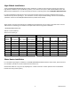
High Altitude Installations The Rinnai RU98i (REU-KB3237FFUD-US) has been certified for use with the CVent Common Exhaust Vent System at high altitude installations up to 10,200 feet. (3,109 m). The common vent system is CSA certified (ANSI Z21.10.3, Gas Water Heaters Standards) for use only with the Rinnai tankless condensing water heater RU98i (REU-KB3237FFUD-US).
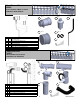
CVent Starter Kit 790005 8-Inch For Back–2-Back or InLine Combustion Air & Exhaust 1 2 NO Qty. 1 3 Qty. 1 5 QTY DESCRIPTION CVENT ENDPIECE (EXHAUST) W/ CLEANOUT & CONDEN1 SATE DRAIN (32mm) 1 2 1 CVENT COMB AIR ENDPIECE D8 3 1 CVENT CONDENSATE TRAP (32mm Connection) 4 1 CVENT DRAIN HOSE 5 2 CVENT DRAIN HOSE CLAMP 6 1 UBBINK INSTALLATION INSTRUCTION 7 1 CENTROCERIN LUBRICANT Qty. 1 Qty. 1 4 Qty.
CVent Back-2-Back Kit 790008 8-Inch Header Kit For Back-2-Back Combustion Air & Exhaust 1 Qty. 1 5 Ø4” Qty. 1 Ø3” Ø4” Qty. 2 Qty. 2 2 3 NO QTY 1 1 CVENT COLLECTOR, 2 CONNECTION, D8 X L20 2 2 CVENT ELBOW D4 X 87° WITH CLEANOUT 3 2 4 2 5 1 CVENT EXTENSION, D4 X L18 CVENT APPLIANCE ADAPTER WITH CHECK VALVE AND TRAP CVENT COMB. AIR COLLECTOR, 2 CONNECTION, D8 X L20 X D3 6 2 CVENT COMB. AIR FLEX FITTING, D3 7 1 CENTROCERIN LUBRICANT 4 6 Qty.
Parts / Kits CVent Common Venting Exhaust / Intake Components (PPtl, polypropylene translucent) Part No. Description Part No.
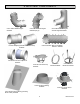
INCH VENT COMPONENTS CVent Elbow D8x90 degree #790023 CVent Elbow D8x45 degree #790022 (Qty.
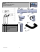
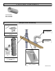
4 INCH VENT COMPONENTS CVent Extension D4xL18 #790035 D4xL39 #790028 Sample Roof Assembly O TI P O L NA Field Supplied PVC Components CVent 8-in Rain Cap #790034 Field Supplied 8” PVC Flashing NOTE: Use PVC adapter (illustrate above) at the combustion air header when transitioning to PVC CVent 8-in Roof Termination Kit with PVC Adapter #790001 Cvent pitched roof moldable flashing #790003 9 Rinnai CVent
Sample Horizontal Termination Assembly Part Number:790027 CVent Elbow D4 x 90 (Qty. 2) Part Number:790020 / 790021 CVent Extension (Qty. 5) Part Number:790004 Wall Termination Kit Combustion Air & Exhaust (Qty 2) Field Supplied PVC Components Part Number: 790005 CVent Starter Kit (Qty. 1) Part Number: 790008 CVent Back-2-Back Kit (QTY. 4) Part Number:790037 Combustion Air PVC Adapter Kit (Qty.
Spare Parts List Included With Kit No. Part No.
Venting Guidelines WARNING The Ubbink Polypropylene CVent can be used on both the combustion air and exhaust. Field supplied PVC material can only be used on the combustion air side and MUST NOT be used for the exhaust. DO NOT Do not install in separate distribution systems. All water heaters common vented must be in the same hot and cold plumbing manifolds and must not exceed 8 units. Do not use PVC, CPVC, ABS or galvanized material for the exhaust vent.
Maximum Equivalent Vent Length In the table below you find the maximum equivalent pipe length of the exhaust and intake venting. When determining equivalent exhaust and intake vent lengths add: • • • 6 feet for each 90° elbow 3 feet for each 45° elbow • Minimum Equivalent Vent Length Add any vent extension lengths which are added within the header due to increased spacing of the water heaters Header kits have already been counted and do not need to be added.
CVent Termination Clearances This appliance along with the CVent Common Vent System is certified with the Cvent 8-in Wall Termination Kit, (790004) mounted in the orientation shown below. Horizontal Termination The exhaust and combustion air terminations must follow these clearances: [1] 12 inch minimum vertically from bottom of exhaust termination to top of intake termination. [2] 12 inch minimum vertically from bottom of combustion air termination to ground or anticipated snow line.
Exhaust Vent Termination Clearances For indoor models, you must install terminations to bring in combustion air and expel exhaust. TERMINATION INSIDE CORNERDETAIL G Clearance in Ref.
Additional clearances Check on whether local codes supersede these clearances. Avoid termination locations near a dryer vent. Avoid termination locations near commercial cooking exhaust. You must install a vent termination at least 12 (0.61 m ) to an inside corner inches above grade or snow line.
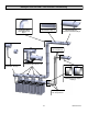
Maintenance Clearances Follow the recommended minimum service clearances below for maintenance access to the header above the water heater. If the vent system is to be enclosed, it is suggested that the design of the enclosure shall permit inspection of the vent system. The design of such enclosure shall be deemed acceptable by the installer or the local inspector. Back to Back Configuration In Line Configuration 30” 42” 42” 36” 5.
Installation Instructions Exhaust Vent Installation Procedures: • • • • • After ensuring the water heaters are mounted securely and spaced 20.5” apart, install the appliance adapter on top of the water heaters. hand cleanout cap Exhaust Venting is designed for a 3° rise. When the water heaters are mounted at 20.5” spacing, the height increase is 1” per water heater. A 4” diameter extension pipe is included with the kit that must be cut to length to account for the rise from unit to unit.
Options for Combustion Air Vent: • • For extended Intake pipe runs, PVC can be used between the Intake Header and Termination. Use the PVC adapter (described below) when transitioning from the PP intake header to the stainless steel Combustion Air Termination. WARNING The materials described below can only be used on the combustion air vent. The Ubbink Polypropylene CVent can be used on both the combustion air and exhaust.
Installation Instructions Refer to the Ubbink appendix of this manual for the vent system assembly instructions. Follow these Rinnai installation instructions in this manual in addition to the Ubbink vent system assembly instructions. Install the venting according to one of the 2 configurations below. Do not locate the common vent remotely from the water heaters. The installation area should be measured to make sure that adequate space is available to install the water heaters and venting system.
Installation Instructions Recommended Spacing of Water Heaters Spacing of the water heaters is critical for the common vent system to mounting easily and securely. The collectors are made for 20.5” spacing (center line to center line) between water heaters. If a different spacing is needed, please contact Rinnai concerning your application. Rinnai recommends using our Tankless Rack System (TRS) which is designed for 20.5” spacing.
Installation Instructions Install the Condensate Trap and Drain Pipe The CVent exhaust header collects condensate. A collector and self-priming trap is included with each starter kit. Additional condensate trap loop assemblies are provided with each appliance adapter. Condensate loops must be primed before operation per the instructions provided below. Condensate must be drained to prevent the malfunction, diagnostic code failures, or property damage. Condensate should be disposed according to local codes.
Common Header Check Valve Maintenance Visually inspect the check valve annually (or after 4000 operation hours) for obstructions, proper operation , large and small particles of debris, according to the instructions below. Operation hours can be obtained on the controller by pressing and holding the down button for 2 seconds and without releasing the down button, press the ON/OFF button. The third number to cycle through will be the operating hours in units of a hundred hours.
Final Checklist □ Reference the Rinnai Water Heater Operation and Installation Manual for proper installation of the Rinnai water heaters. □ □ Clearances from the water heater unit are met. □ Ensure you have used the correct venting products and that you have completely followed the venting manufacturer’s installation instructions and these installation instructions. □ Verify that the vent system does not exceed the maximum equivalent length for allowed. □ Verify that dip switch No.
Appendix A Ubbink CVent Condensing Common Vent System Installation and Assembly Instructions Warranty and Liability Claims for personal and material damages are excluded, if they are due to any or several of the following reasons: • Use of the CVent system not in accordance with the regulations. • Improper assembly and incorrect operation. • Faulty maintenance. • Non-compliance with the assembly and operating instructions. • Non-approved structural changes to the unit or to the individual components.
List of Contents A1 A2 A3 A4 A5 A6 A7 A8 A9 A10 A11 A12 A13 A14 A15 A16 A17 A18 Preface General and Local standards information Risk guidelines Transport and storage Tools and Workmanship General assembling Instructions Condensate and condensate drain Instructions to be complied with List of components Preliminary works on the chase Preparation, calculation and planning Inspection during assembly Position of side connections of common header Installation and maintenance of the Check Valves Clearances of br
A2 General and Local standards information When installing and operating the CVent Common Vent System, the following valid standards and regulations must be complied with and adhered to: • Local codes or, in the absence of local codes, with the National Fuel Gas Code, ANSI Z223.1/NFPA 54, or the Natural Gas and Propane Installation Code, CSA B149.1.
2 inches ) ( A6 General Assembly Instructions Correct Pitch The pipes and formed parts must be installed at an angle of 3° incline towards the heating appliance, to allow the condensate to dispose in accordance with regulations. Note: 3° Pitch equals a height difference of 2 inches per 3ft (5.6 cm/meter) 3 ft ( ) Lubricant The seals and male ends of all CVent common vent components must be lubricated before assembly.
A7 Condensate and condensate drain • • Condensate is produced in the CVent Common Vent System when appliances are operating. • The disposal for the condensate can be accommodated via the appliances and / or separate condensate outlets in the CVent Common Vent System. A condensate trap must be installed at any drain point to prevent flue gasses from exiting.
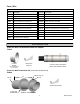
28.1” A8 Vertical Termination Assembly Description Material 1 Storm Collar (8in) Stainless 1 2 Terminal Cap Stainless 1 3 8” Exhaust Extension (Black) Plastic 1 4 8” Inner Exhaust Assembly (With (2) 8” CVent Distancers) Plastic 1 5 Terminal Clamp Ring Stainless 1 6 Terminal Outer Shell Stainless 1 7 Terminal Base Stainless 1 8 Termination Clamp Galvanized 1 General ments ,Remarks and Tools: Qty. 11.83” 56.
A9 Final Installation Check List All vent components are secure and fully engaged. All seals are correctly positioned and included at every joint. All exhaust vent runs include a minimum of a 3° incline (3/4” per ft or 5.6cm/m) All Condensate drains tubes are connected to a drain and comply with local code. All condensate traps have been primed. There are no obstructions in the combustion air or exhaust vent runs.
A14 Installation and maintenance of the check valves •The Check Valves must be Installed vertically as first component over the appliance, and are part of the installation kit. •For B-type installations (room air dependent) the air intake spigot can be protected for debris with a grid, for C-type appliances (closed system) the air inlet system can be connected to the spigot. •The valves must be inspected and checked annually, or after 4000 operation hours.
A18 Application Manufacturer’s Information The manufacturer’s identification information as displayed below must be filled out and kept with the system chimney.
Rinnai America Corporation • 103 International Drive, Peachtree City, GA 30269 Toll-Free: 1-800-621-9419 • Phone: 678-829-1700 • www.rinnai.us ©2013 Rinnai America Corporation. Rinnai is continually updating and improving products; therefore, specifications are subject to change without prior notice. Local, state, provincial, federal and national fuel gas codes must be adhered to prior to and upon installation.