Operation / Installation Manual RINNAI ‘PRESTIGE’® and RINNAI ‘SUNMASTER’® Solar Split Systems Electric and Gas Boosted AS 2712 Lic No.1849 SAI Global All Rinnai gas products are A.G.A. certified. WARNING W169 SAI Global The collector flow and return pipes should be 15mm copper tube or alternative tube supplied by Rinnai. Plastic pipe must not be used. Plastic pipe is not suited to the high water temperatures and pressures that may occur in the collector flow and return system.
NOTES
TABLE OF CONTENTS IMPORTANT INFORMATION & WARNINGS...........................................................................................................2 SAFETY & REGULATORY INFORMATION...............................................................................................................................2 SCALDS HAZARDS ..................................................................................................................................................................
IMPORTANT INFORMATION & WARNINGS SAFETY & REGULATORY INFORMATION DO NOT operate this system before reading the manufacturers instructions. WARNING This appliance must be installed, commissioned and serviced by an authorised person in accordance with all applicable local rules and regulations. Access covers of water heating system components will expose 240V wiring and MUST be removed by an authorised person.
IMPORTANT INFORMATION & WARNINGS SCALDS HAZARDS HOT WATER CAN CAUSE SCALDS. CHILDREN, DISABLED, ELDERLY AND THE INFIRM ARE AT THE HIGHEST RISK OF BEING SCALDED. FEEL WATER TEMPERATURE BEFORE BATHING OR SHOWERING. SCALDS FROM HOT WATER TAPS CAN RESULT IN SEVERE INJURIES TO YOUNG CHILDREN. SCALDS OCCUR WHEN CHILDREN ARE EXPOSED DIRECTLY TO HOT WATER WHEN THEY ARE PLACED INTO A BATH WHICH IS TOO HOT. ALWAYS......
IMPORTANT INFORMATION & WARNINGS OPERATION PRINCIPLE This system is designed to have the solar collectors on the roof and the storage cylinder installed at ground or floor level.Electric and Gas boosted models are available. The system comprises a hot water storage cylinder, solar collectors, pump circulation system solar control unit and temperature sensors.
IMPORTANT INFORMATION & WARNINGS SAFETY DEVICES The water heating system is supplied with various safety devices including temperature sensors, overheat sensors and switches and a Pressure & Temperature Relief (PTR) valve. These devices must not be tampered with or removed. The water heating system must not be operated unless each of these devices is fitted and is in working order. DO NOT tamper with or remove safety devices.
IMPORTANT INFORMATION & WARNINGS Gas boosted models • Do not touch the flue outlet or do not insert any objects into the flue outlet. • Keep flammable materials, spray cans, fuel containers, trees, shrubs and pool chemicals etc. well clear of the flue outlet. • Do not use the gas types other than those designated on the data plate. For example, do not use Propane/Butane gas mixtures on appliances marked Propane Gas. • Do not use Propane gas on appliances marked as Natural gas and vice versa.
IMPORTANT INFORMATION & WARNINGS WATER QUALITY The water quality of most public supplies is suitable for the water heating system. The water quality from bore wells is generally unsuitable for the water heating system. Refer to separate 'Warranty Terms and Conditions' document for water quality parameters and how they affect the warranty conditions. If in doubt about the water quality, have it checked against the parameters listed in the warranty conditions.
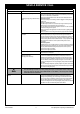
SAVE A SERVICE CALL Table 1 - Troubleshooting Problem Insufficient or no hot Water Cause Remedy Booster heating not operating Or Insufficient gas supply for gas boosted heating system Excessive hot water consumption Electric Boosted Systems: If the water goes cold, are you using more hot water than you think? Often end users are surprised at the amount of hot water used, especially when showering.
SAVE A SERVICE CALL Problem Cause Remedy Insufficient or no hot Water continued Booster element Thermostat Settings Electric Boosted Systems: The end user can check the temperature of hot water delivered with a thermometer placed under the closest non tempered outlet (usually the kitchen sink). CAUTION: Take care to avoid scalding. This test should be done early in the morning after overnight electrical boosting before any hot water is used.
SPECIFICATIONS FOR SYSTEMS GENERAL Split solar hot water systems are specified according to the grade of storage cylinder material, cylinder capacity, number of solar collectors and boost type and capacity. Boost capacity for gas boosted system depends on the gas booster model selected. Boost capacity for electrically boosted systems depends on the power rating of electric heating elements and whether one or two electric heating elements are fitted.
SPECIFICATIONS FOR SOLAR COLLECTORS Table 3 - Model Numbers and Specifications MODEL NUMBERS AND SPECIFICATIONS CHARACTERISTICS Enduro / Equinox (SP200A) or (SP200A FTC) Excelsior (EXT OR EXT FTC) E-FROST (HPFTC- 8-10) TYPE Flat plate Flat plate Flat Plate / Heat Pipe - Waterways Copper Copper Copper - Absorber Aluminium Copper Aluminium - Selective Surface High Performance Sputtered Titanium Oxide High Performance CONSTRUCTION Maximum Operating Pressure 850 kPa Casing Material Alu
SPECIFICATIONS FOR STORAGE CYLINDERS SUNMASTER - ELECTRIC - VITREOUS ENAMEL SE160 SE200 SE315 PTR / Solar Return / Hot Water Outlet 1310 1605 1200 Flow line to Collectors 665 665 700 Cold Water Inlet 225 225 260 Cylinder Height 1530 1825 1510 Diameter 515 515 685 Weight Empty (kg) 71 83 100 CYLINDER HEIGHT HOT WATER OUTLET P&TR VALVE COLD WATER INLET FLOW LINE TO COLLECTORS PTR / SOLAR RETURN SOLAR RETURN CYLINDER DIAMETER TEMPERATURE SENSOR DRY WELL Figure 4 - Dimensiona
SPECIFICATIONS FOR STORAGE CYLINDERS SUNMASTER GAS - VITREOUS ENAMEL SG175 SG215 SG270 SG340 Cylinder Height 1530 1825 1265 1510 PTR / Solar Return 1310 1605 985 1200 Flow line to collectors 665 665 700 700 Cold Water Inlet 225 225 260 260 Gas Supply and Hot Water Outlet 940 1235 675 920 Gas Booster Flue Outlet 1400 1695 1135 1380 Diameter 515 515 685 685 Weight Empty (kg) 66 88 95 103 GAS BOOSTER FLUE OUTLET GAS SUPPLY AND HOT WATER OUTLET P&TR VALVE COLD WATE
SPECIFICATIONS FOR STORAGE CYLINDERS PRESTIGE ELECTRIC - STAINLESS STEEL PRESTIGE ELECTRIC 160 250 315 1490 1880 Cylinder Height 1205 1700 2090 Weight Empty (kg) 44 56 68 SOLAR RETURN CYLINDER HEIGHT 995 P&TR VALVE & HOT WATER OUTLET PTR / Solar Return / Hot Water Outlet 650 300 210 600 COLD WATER INLET Figure 6 - Dimensional Drawing - Rinnai Prestige Stainless Steel Storage Cylinder - Electric Boosted Split systems Rinnai Australia - 14 - Solar Split Systems Operating / Installati
SPECIFICATIONS FOR GAS BOOSTERS Table 4 - Specifications - Gas Boosters Model Name: S20 S26 Boost Capacity: - L/min. @ 20°C rise - L/min @ 25°C rise (L/min) 20 16 26 24 Maximum Rated Flow: (L/min) 20 26 Minimum Supply Pressure for Maximum rated flow: (kPa) 120 200 (L/min) 2.4 2.4 Yes Yes 125 - 18 188 - 23 Star Rating (AS 4552 - 1998): 5.5 5.
INSTALLATION & MAINTENANCE - ALL SYSTEMS REGULATIONS AND OCCUPATIONAL HEALTH AND SAFETY (OH&S) WARNING Installation and commissioning must be performed by authorised persons. Solar systems must be installed in accordance with these instructions and all regulatory requirements which exist in your area including those in relation to manual lifting, working at heights and on roofs.
INSTALLATION & MAINTENANCE - ALL SYSTEMS GAS BOOSTER LOCATION AND MOUNTING (where applicable) The gas booster is designed for 'Outdoor' Installation only. As such, it must be located in an above ground open air situation with natural ventilation, without stagnant areas, where gas leakage and products of combustion are rapidly dispersed by wind and natural convection.
INSTALLATION & MAINTENANCE - ALL SYSTEMS VALVES & FITTINGS The following valves and fittings are supplied with your solar hot water system: • A combined pressure and temperature (PTR) relief valve, capacity 10 kW. Relief valve pressure settings vary with models. This valve is fitted at the top of the storage cylinder. The PTR valve is a safety device and it is mandatory that it is fitted by the installer in all installations.
INSTALLATION OF SOLAR COLLECTORS REGULATIONS AND OCCUPATIONAL HEALTH AND SAFETY (OH&S) Installation and commissioning must be performed by authorised persons. Rinnai solar systems must be installed in accordance with these Instructions and all regulatory requirements which exist in your area including those in relation to manual lifting, working at heights and on roofs.
INSTALLATION OF SOLAR COLLECTORS Table 6: Latitudes of Australian Cities City Adelaide Alice Springs Brisbane Broken Hill Latitude 35°S 24°S 27°S 31°S City Cairns Canberra Darwin Geraldton Latitude 17°S 35°S 12°S 28°S City Hobart Mildura Melbourne Perth Latitude 42°S 34°S 38°S 32°S City Port Hedland Rockhampton Sydney Townsville Latitude 20°S 24°S 34°S 19°S For all installations the collector bank must slope upwards approximately 8 mm per collector from inlet to outlet as shown below: HOT CONNECTION
INSTALLATION OF SOLAR COLLECTORS SOLAR COLLECTOR INSTALLATION COMPONENTS Table 7 - Components for installing Collectors COLLECTOR MOUNTING COMPONENTS (supplied in Collector Installation kit) 1 Number of Collectors 2 3 2 - - 1 2 - Number of Collectors 2 3 Mounting Rail Small 14201196 - COLLECTOR CONNECTING COMPONENTS (supplied in Collector Installation kit) 2 2 2 Stop End (1 x plug ¾G (Kinco) + 1 x ¾ Kinco nut and olive) (Not used with E-Frost Collector) Mounting Rail Medium 14201197 - -
INSTALLATION OF SOLAR COLLECTORS STANDARD INSTALLATION Collector Mounting Component Pre Assembly for a Standard Installation • Assemble the collector rail components as shown in Figure 14 below. • Only loosely attach the collector retainers to the rails.
INSTALLATION OF SOLAR COLLECTORS STANDARD INSTALLATION CONTINUED Fastening (Collectors to a Metal Roof) This installation is not suitable for in cyclonic areas. For further details, please contact your local Rinnai Solar distributor. NOTE • Position the lower collector mounting rail Tiles removed assembly so that the rail is angled to ensure the collectors have an 8 mm / collector rise. • For aesthetic reasons it is best to mount as close as possible to the gutter.
INSTALLATION OF SOLAR COLLECTORS STANDARD INSTALLATION CONTINUED Fastening (Collectors to a Tiled Roof) This installation is not suitable for use in cyclonic areas. For further details, please contact your local Rinnai Solar distributor. NOTE • Position the lower collector mounting rail Bolt lower mounting rail to roof purlin using a suitable fastener assembly so that the rail is over the roof purlin and the rail is angled ensure the collectors have an 8 mm / collector rise.
INSTALLATION OF SOLAR COLLECTORS NOTE This installation is not suitable use in cyclonic areas. For the correct frame for use in cyclone areas, contact your local Rinnai Solar distributor. FRAMED INSTALLATIONS - FLAT ROOF FRAMES Table 7 - Framed Installations • Assemble the flat roof frame as shown in the diagram • ‘TO PH AT ’ SE CT IO N • FLAT ROOF FRAME • • supplied with the flat roof frame kit using the bolts, nuts and washers supplied.
INSTALLATION OF SOLAR COLLECTORS FRAMED INSTALLATIONS - CYCLONE FRAME Assemble cyclone frame and mount collectors as described in instructions provided with cyclone frame kit. COMMERCIAL INSTALLATIONS Commercial system comprise of multiple of 2-3 collectors joined together. Figure 22 shows the roof spacing required for the collector sets. Figures 23 and 24 shows the flow and return piping layout for multiple collector sets.
INSTALLATION OF SOLAR COLLECTORS Figure 22 - Commercial Collector Installation Rinnai Australia - 27 - Solar Split Systems Operating / Installation Manual
INSTALLATION OF SOLAR COLLECTORS Figure 23 - Flow and Return Lines for Commercial Systems HOT SENSOR SHEATH ON OUTLET OF ONE SET OF PANELS Figure 24 - E-Frost Collectors Rinnai Australia - 28 - Solar Split Systems Operating / Installation Manual
INSTALLATION OF SOLAR COLLECTORS COLLECTOR FITTINGS INSTALLATIONS COLD FLOW PIPE SUPPLIED BY INSTALLER 1/2" TO 3/4" UNION STOP END COMPRESSION UNION COMPRESSION UNION STOP END 1/2" NUT 1/2" OLIVE RETURN PIPE SUPPLIED BY INSTALLER HOT SENSOR SHEATH AIR BLEED VALVE HOT SENSOR LEAD Connect the fittings to the collectors as shown in the diagrams below: Figure 25 - Collector Fitting Details (Enduro, Equinox and Excelsior Collectors) Rinnai Australia - 29 - Solar Split Systems Operating / Installa
Rinnai Australia COLD FLOW PIPE SUPPLIED BY INSTALLER 1/2" TO 3/4" UNION 3/4" COMPRESSION UNION - 30 - 1/2" OLIVE 1/2" NUT HOT SENSOR LEAD AIR BLEED VALVE HEADER PIPE MUST BE AT TOP TO ENSURE COLLECTOR OPERATION RETURN PIPE SUPPLIED BY INSTALLER HOT SENSOR SHEATH INSTALLATION OF SOLAR E-FROST COLLECTORS Figure 26 - Collector Fitting Details (E-Frost Collectors) Solar Split Systems Operating / Installation Manual
INSTALLATION & MAINTENANCE - GAS BOOSTED OVERVIEW OF SYSTEM COMPONENTS The range of gas boosted solar hot water systems include all the components shown in Figure 27 - 30 (refer to the appropriate Figure depending on cylinder type/size and kit on the following pages). The pump kit and associated plumbing connections are factory pre-assembled. All other components and fittings will require connection on site.
INSTALLATION & MAINTENANCE - GAS BOOSTED SYSTEMS CLEARANCES Figure 5.3 is reproduced below. Note that AS 5601-2004 was current at time of printing but may have been superseded. It is the installer’s responsibility to ensure current requirements are met. AS 5601 - Figure 5.
INSTALLATION & MAINTENANCE - GAS BOOSTED SYSTEMS GAS BOOSTER MOUNTING Sunmaster Step 1. Mount upper mounting bracket using template provided. (SG175 - SG215 are factory mounted) Step 2. Fix lower mounting bracket to Booster using screws provided. Step 3. Hang booster on bracket and secure with screws provided. Step 4. Secure lower mounting bracket to cylinder using screws provided.
INSTALLATION & MAINTENANCE - GAS BOOSTED SYSTEMS Sunmaster - 3' OR 3' WITH SGPKIT 2 1 3 13 10 3 15 12 16 14 11 16 13 14 15 11 12 10 9 8 3 5 6 7 Figure 27 - Sunmaster Gas SG175 or SG215 with SGPKIT Rinnai Australia - 34 - Solar Split Systems Operating / Installation Manual
INSTALLATION & MAINTENANCE - GAS BOOSTED SYSTEMS Sunmaster SG175 or SG215 with SGPKIT Items Supplied with Cylinder Items Supplied in SGPKIT (cont…) 1 PTR Valve 1 1 Adaptor R ¾ x Rp ½ Pump and Controller Assembly (includes 2 x ½ Kinco nut and olive, flow control valve and non return valve) Temperature sensor lead (31002710) included with assembly, but shown separately as item 12 for clarity 39001735 3 Nipple R ¾ 1 Temperature Sensor with 2 m lead 2 Part of Pump and Controller Assembly (39001735), bu
INSTALLATION & MAINTENANCE - GAS BOOSTED SYSTEMS Sunmaster - 3' OR 3' WITH SGPKIT2 2 1 3 13 10 3 15 12 16 14 11 17 14 16 15 11 12 8 3 6 5 Figure 28 - Sunmaster Gas SG175 or SG215 with SGPKIT2 Rinnai Australia - 36 - Solar Split Systems Operating / Installation Manual
INSTALLATION & MAINTENANCE - GAS BOOSTED SYSTEMS Sunmaster SG175 or SG215 with SGPKIT2 Items Supplied with Cylinder Items Supplied in SGPKIT2 (cont…) 1 1 Pump and Controller Assembly PTR Valve (includes 2 x ½ Kinco nut and olive, flow control valve and non return valve) Temperature sensor lead (31002710) included with assembly, but shown separately as item 12 for clarity 39001735 1 Adaptor R ¾ x Rp ½ 1 3 Temperature Sensor with 2 m lead Part of Pump and Controller Assembly (39001735), but shown separ
INSTALLATION & MAINTENANCE - GAS BOOSTED SYSTEMS Sunmaster SG270 - SG340 with SGPKIT 270 2 1 4 3 13 10 3 16 15 12 14 11 16 13 14 15 11 12 10 9 8 3 4 5 6 7 Figure29 - Sunmaster Gas SG270 or SG340 with SGPKIT270 Rinnai Australia - 38 - Solar Split Systems Operating / Installation Manual
INSTALLATION & MAINTENANCE - GAS BOOSTED SYSTEMS Items Supplied with Cylinder Items Supplied in SGPKIT270 (cont…) ! # $ % & ' ( ) * # $ * + , * - )% - * ' (+ ' %.
INSTALLATION & MAINTENANCE - GAS BOOSTED SYSTEMS Sunmaster SG270 and SG340 with SGPKIT3 2 1 3 4 13 10 3 15 12 16 14 11 17 14 15 16 12 11 8 3 9 Figure 30 - Sunmaster Gas SG270 - SG340 with SGPKIT3 Rinnai Australia - 40 - Solar Split Systems Operating / Installation Manual
INSTALLATION & MAINTENANCE - GAS BOOSTED SYSTEMS Sunmaster SG270 and SG340 with SGPKIT3 Items Supplied with Cylinder Items Supplied in SGPKIT3 (cont…) 1 1 PTR Valve 1 Elbow ¾ Rp x ¾ G flexi 21201012 Fibre Washer ¾ 17401008 Insulated Flexi Pipe 1080 mm 11601069 2 Adaptor R ¾ x Rp ½ 3 Adaptor R ¾ x Rp ¾ 1 Items Supplied in SGPKIT3 1 R ¾ Nipple 17201005 1 2 Cold Inlet Copper T 11603921 Gas Booster Mounting Brackets 1 x tabs bent 26601098 1 x tabs unbent 26601096 1 G3/4 (Comp) x R ¾ union 322
INSTALLATION & MAINTENANCE - GAS BOOSTED SYSTEMS INSTALLATION PROCEDURE Install Solar Collectors Position and install the solar collectors in accordance with the section ‘INSTALLATION SOLAR COLLECTORS”. 1. Position Storage Cylinder Position the hot water storage cylinder on a level base in accordance with the section ‘STORAGE CYLINDER LOCATION’. 2. Connect PTR Valve • Connect the PTR Valve in the location shown in the relevant diagram of Figures 27 to 30. Leave the valve outlet pointing down.
INSTALLATION & MAINTENANCE - GAS BOOSTED SYSTEMS 7. Cold Water Supply • Connect cold water supply to the inlet ‘T’. Ensure that the relevant valves as described in the section “VALVES AND FITTINGS” are fitted. • Purge the cold water supply lines to remove air and swarf before final connection. 8. Relief Drain Lines • Independent 15 mm copper pipes must be fitted to the drain outlets of the PTR and ECV.
INSTALLATION & MAINTENANCE - GAS BOOSTED SYSTEMS CHECKING SOLAR PUMP OPERATION 1. Ensure hot and cold sensors are connected as shown Figure 31. 2. Activate power supply. 3. Pumps will operate when solar energy is available to be collected. Pump operation can be checked by placing the end of a screw driver to the pump body and the other end of the screw driver near your ear. The dip switches within the pump control box should not need to be adjusted.
INSTALLATION & MAINTENANCE - GAS BOOSTED SYSTEMS PRE SOLAR HEATING CHECKS Before commencing solar heating of the water in the system ensure the following actions have been completed: Solar Collectors 1. Are the solar collectors installed with the correct slope and orientation to the sun? 2. Is the installation finished neatly with the roof made good, all tiles and flashings in place? 3. Are the bolts tight on the roof framework? 4.
INSTALLATION & MAINTENANCE - GAS BOOSTED SYSTEMS Temperature Limiting Devices 1. Commission any temperature limiting devices in accordance with the instructions supplied by the manufacturer. 2. Confirm the hot water delivery temperature at a tempered water outlet. Tempered water outlets should be those supplying areas primarily used for the purposes of personal hygiene such as bathrooms.
INSTALLATION & MAINTENANCE - ELECTRIC BOOSTED SYSTEMS OVERVIEW OF SYSTEM COMPONENTS The range of electric boosted solar hot water systems include all the components shown in (Refer to the appropriate figure depending on cylinder type / size and kit). The pump kit and associated plumbing connections are factory pre-assembled. All other components and fittings will require connection on site.
INSTALLATION & MAINTENANCE - ELECTRIC BOOSTED SYSTEMS Sunmaster SE160, SE200 or SE315 WITH SEPKIT 2 1 3 3 11 10 12 9 8 3 4 5 6 7 Figure 34 - Sunmaster Electric SE160, SE200 or SE315 with SEPKIT Rinnai Australia - 48 - Solar Split Systems Operating / Installation Manual
INSTALLATION & MAINTENANCE - ELECTRIC BOOSTED SYSTEMS Sunmaster SE160, SE200 or SE315 with SEPKIT Items Supplied with Cylinder Items Supplied in SEPKIT (cont…) 1 PTR Valve 1 1 Pump and Controller Assembly (includes 2 x ½ Kinco nut and olive, flow control valve and non return valve) Temperature sensor lead (31002710) included with assembly, but shown separately as item 12 for clarity 39001735 Adaptor R ¾ x Rp ½ 3 Adaptor R ¾ x Rp ¾ Items Supplied in SEPKIT 1 R ¾ Nipples 17201003 (*1 not needed) * 1
INSTALLATION & MAINTENANCE - ELECTRIC BOOSTED SYSTEMS Sunmaster SE160, SE200 or SE315 with USKIT1 2 1 3 3 11 12 8 3 9 Figure 35 - Sunmaster Electric SE160, SE200 or SE315 with USKIT1 Rinnai Australia - 50 - Solar Split Systems Operating / Installation Manual
INSTALLATION & MAINTENANCE - ELECTRIC BOOSTED SYSTEMS Sunmaster SE160, SE200 or SE315 with USKIT1 Items Supplied with Cylinder Items Supplied in USKIT1 1 1 PTR Valve 1 Adaptor R¾ x Rp½ 3 Cold Inlet Copper T 11603921 G3/4 (Comp) x R ¾ union 32201713 1 Adaptor R¾ x Rp¾ 1 Pump and Controller Assembly (includes 2 x ½ Kinco nut and olive, flow control valve and non return valve) Temperature sensor lead (31002710) included with assembly, but shown separately as item 12 for clarity 39001735 1 Temperat
INSTALLATION & MAINTENANCE - ELECTRIC BOOSTED SYSTEMS Prestige Electric with USKIT 2 1 11 4 10 12 8 9 3 Figure 36 - Split Prestige Electric with USKIT1 Rinnai Australia - 52 - Solar Split Systems Operating / Installation Manual
INSTALLATION & MAINTENANCE - ELECTRIC BOOSTED SYSTEMS Prestige MkII Electric with USKIT1 Items Supplied with Cylinder Items Supplied in USKIT1 1 PTR Valve 11004784 1 1 Hot outlet T 19001018 Cold Inlet Copper T 11603921 1 T ¾ Rp 19001011 1 1 1 Nipple R ¾ 17201005 250 mm Sheath Thermocouple 10204721 G3/4 (Comp) x R ¾ union 32201713 1 Pump and Controller Assembly (includes 2 x ½ Kinco nut and olive, flow control valve and non return valve) Temperature sensor lead (31002710) included with as
INSTALLATION & MAINTENANCE - ELECTRIC BOOSTED SYSTEMS INSTALLATION PROCEDURE 1. Install Solar Collectors Position and install the solar collectors in accordance with the section ‘INSTALLATION OF SOLAR COLLECTORS’. 2). Position Storage Cylinder Position the hot water storage cylinder on a level base in accordance with the section “STORAGE CYLINDER LOCATION” 3. Connect PTR Valve • Connect the PTR Valve in the location shown in the relevant diagram of Figures 34 to 36. Leave the valve outlet pointing down.
INSTALLATION & MAINTENANCE - ELECTRIC BOOSTED SYSTEMS 7. Cold Water Supply • Connect cold water supply to the inlet ‘T’. Ensure that the relevant valves as described in the section “VALVES AND FITTINGS” are fitted. • Purge the cold water supply lines to remove air and swarf before final connection. 8. Relief Drain Lines • Independent 15 mm copper pipes must be fitted to the drain outlets of the PTR and ECV.
INSTALLATION & MAINTENANCE - ELECTRIC BOOSTED SYSTEMS 11).Connections for single element heaters Figures 17 & 18 shows the wiring detail for single and twin element heaters. Figure 37 - Wiring detail - single element heaters Figure 38 - Wiring detail for twin element heaters A flexible 20 mm conduit is required for the electrical cable to the storage cylinder. The conduit is to be connected to the unit with a 20mm terminator.
INSTALLATION & MAINTENANCE - ELECTRIC BOOSTED SYSTEMS FILLING THE SYSTEM CAUTION Ensure building occupants are warned to stay clear of the solar system components, building perimeter and roof since hot water or steam may be discharged from pipes or components. 1. Ensure the electric power supplies to the water heater and pump kit are switched ‘OFF’. 2. Ensure the gas supply to the continuous flow water heater is isolated. 3. Turn ‘ON’ the hot water tap at the sink.
INSTALLATION & MAINTENANCE - ELECTRIC BOOSTED SYSTEMS Table 10 - Optimum Flow Rate (Litres/min). No. of Collectors Zones 1, 2 & 3 Zone 4 1 0.50 0.50 2 1.00 0.65 3 1.25 1.00 Electric Boosted PRE SOLAR HEATING CHECKS Before commencing solar heating of the water in the system ensure the following actions have been completed: Solar Collectors 1. Are the solar collectors installed with the correct slope and orientation to the sun? 2.
INSTALLATION & MAINTENANCE - ELECTRIC BOOSTED SYSTEMS 1. The power supply to the element and pump controller must be switched off and fuse(s) removed. 2. Close the cold water mains supply stop cock. 3. Open a hot tap to relieve pressure. 4. Disconnect the hot outlet near the top of the storage cylinder. 5. Disconnect the cold inlet near the bottom of the storage cylinder. 6. Disconnect the connection between the solar 'flow pipe' and solar pump. 7.
NOTES
NOTES
CONTACT INFORMATION Australia Pty. Ltd. Internet: www.rinnai.com.au E-mail: enquiry@rinnai.com.au ABN 74 005 138 769 Head Office 10-11 Walker Street, Braeside, Victoria 3195 P.O. Box 460 Tel: (03) 9271 6625 Fax: (03) 9271 6622 Spare Parts & Technical Info Tel: 1300 555 545* Fax: 1300 300 141* Rinnai has a Service and Spare Parts network with personnel who are fully trained and equipped to give the best service on your Rinnai appliance.