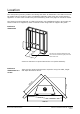
Symmetry RDV3610 Installation Manual Not intended as a fireplace insert Appliance (including flue) is installed after framing and before cladding. Rinnai strongly recommend appliance is fully tested before any cladding materials are applied. Cladding must be installed up to the flange and not over it. Any overhang will alter the performance of the appliance and cause an unsafe situation. Appliance must be installed with a Rinnai supplied flue system.
Contents Before installation 3 Specification 3 Dimensions 4 Location 5 Clearances 6 Mantels, surrounds, and hearths 7 TV installation above a fireplace 8 Installation guide overview 9 Building the frame 10 Electrical connection 10 Bracket installation 11 Fixing the unit to the frame 12 Flue installation - Rinnai flue kits 13 Flue installation - Rinnai flue components 15 Flue installation - 45 degree offsets 16 Flue installation - general guidelines 17 Flue installation - vert
Before installation Unpack the appliance and components and check for damage. DO NOT install any damaged items. Check all components have been supplied and that you have the correct gas type. Read these instructions to get an overview of the steps required before starting the installation. Failure to follow these instructions could cause a malfunction of the appliance. This could result in serious injury and property damage.
Dimensions (mm) 510 310 1090 715 149 Rinnai New Zealand Limited 750 775 845 500 400 995 890 1060 4 RDV3610 Installation Manual: 11658-E 05-10
Location The main points governing location are flueing and warm air distribution. The heater must not be installed where curtains or other combustible materials could come into contact with the appliance. In some cases curtains may need restraining. Refer next page for clearance details. The heater must be positioned on a flat level surface. For installations further up the wall, the heater needs to be supported, either construct a base using board or support with joists. 850 mm min.
Clearances The appliance must not be installed where curtains or other combustible materials could come into contact with the heater. In some cases curtains may need restraining. The clearances listed below are minimum clearances unless otherwise stated. There are further details on mantel and surround clearances on the next page.
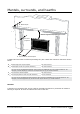
Mantels, surrounds, and hearths B - Mantel depth Min Vertical Clearance 400mm AMinimum - Mantel height from top of fireplace D - Surround projection C - Surround from side of fireplace A mantel and surround are allowed providing they are outside the minimum clearances shown below. A Mantel height from top of fireplace 400 mm minimum B Mantel depth at 400 mm (vertical clearance) 300 mm maximum For every 50 mm of added mantel depth, there must be an additional 100 mm of vertical clearance.
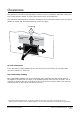
TV installation above a fireplace If installing a flat screen TV above the fire the main issue is heat. Heat from the fire and heat from the flueing components that sit behind the TV, especially if recessed. The Symmetry RDV3610 has fan that distributes warm air from the top of the appliance out into the room. As warm air is dispersed outwards as opposed to directly upwards, installation of a TV may be an option.
Installation guide overview This overview is intended to provide installation information at a high level. Further detail on each of the steps are provided in the following pages. Build frame and complete electrical connection. Install brackets, Symmetry unit and fix unit to frame. Install flue and complete gas connection. Install ducting kit (if purchased) and gas pipe. Install flue restrictor (if required), log set, test pressures and establish flame pattern.
Building the frame Using the dimension drawing below and the information on pages 5-8, construct a frame. A 25 mm clearance is required around the unit (sides and back). 850 mm min. IMPORTANT . in m 1100 40 m m The 540 mm minimum dimension will give a 25 mm clearance (plus) from the back of the unit. 5 - 11 25 m m Electrical connection 25 0m m The standard electrical connection is to the right side of the front of the appliance.
Bracket installation Install the four metal mounting brackets supplied onto the Symmetry RDV3610. The position of the brackets will depend on the cladding thickness and type of installation (framed or frameless). The Symmetry RDV3610 can be installed with the Rinnai granite and metal frames, and also as a frameless installation. The frameless installation can have brick, rock veneer, or tiles, these sit tight up against the framing plate of the fireplace.
Fixing the unit to the frame The Symmetry RDV3610 comes pre-assembled with the burner already in position. For all installations the unit MUST BE positioned on a level surface. 1. Position the unit inside the cavity. 2. Bend and secure the two metal stand-offs supplied with the unit into position. These provide the required 150 mm minimum vertical clearance to the upper lintel. 3. Fix unit to frame with the four mounting brackets.
Flue installation - Rinnai flue kits Rinnai Symmetry RDV3610 flue kits have been based on the flue configurations shown. If you have a combined vertical and horizontal flue configuration you can order separate components to suit. Vertical Flue Horizontal Flue Roof cowl (high wind) Flue pipe short (1 x 300 mm) or Flue pipe long (2 x 230 mm) Wall terminal (square) 90 ° elbow Flashing collar Flashing box Horizontal flashing kit Flue pipe 600 mm Wall strap Flue pipe 1.
Flue installation - Rinnai flue kits Symmetry RDV3610 horizontal flue kits and dimensions The following diagram explains the components, dimensions (mm) and appropriate flue kits available for differing horizontal flue installations. Refer to the 'Distance from Appliance to the Cowl' table to calculate what flue pipe length and/or kit you may need.
Flue installation - Rinnai flue components RDV3610 Flue Elbow 90° Bend (R3643) RDV3610 Flue Elbow 45° Bend (R3642) Bends - effective length Once joined effective length reduces 35 mm: 108 • • 90° = 130 mm 45° = 73 mm 108 165 165 Used to facilitate vertical and horizontal flueing. Elbow swivels 360 ° at base. Angle not adjustable. Offsets obstructions as needed. Elbow swivels 360 ° at base. Angle not adjustable. Comes packaged as a set of two.
Flue installation - 45 degree offsets Flue pipe (length and code) Offset (mm) Rise (mm) None (bend to bend) N/A 124 340 150 mm R3630 203 419 230 mm R3631 257 473 300 mm R3632 311 527 450 mm R3633 417 633 600 mm R3684 524 740 1.
Flue installation - general guidelines Every gas fireplace requires a flue system that will draw effectively and clear flue products safely under all potential wind and climatic conditions. It is the responsibility of the installer to ensure that the appliance is provided with an effective flue. Some guidelines to assist with flue design are listed below.
Flue installation - general guidelines Flue terminal locations Must be compliant with ‘Clearances Required for Flue Terminals’ from NZS 5261 2003. Flue is not to terminate under floors or in a roof space. Minimum and maximum horizontal flue length Each flueing configuration is subject to flueing restrictions, refer to following pages for further detail.
Flue installation - vertical termination For vertical flue terminations with or without 45 ° bends (maximum of two). The shaded sections determine the position of the flue restrictor. Max. 5.4 m Restrictor position # 2 4.2 m Restrictor position # 3 3.0 m Restrictor position # 4 1.8 m No restrictor Min. 0.6 m If bend is less than 45 O, the installation is deemed a vertical termination with 90 O bends (refer next page) Max. 1.
Flue installation - vertical termination For vertical flue terminations with two 90 ° bends (maximum of two). The shaded sections determine the position of the flue restrictor. Horizontal runs of flue pipe must be supported to prevent any downward sags. Horizontal pipe sections should be supported at least every 1.2 m. Wall straps can be used for this purpose. The horizontal run of flue pipe must have a 20 mm rise for every 1 m of run towards the termination. Never allow the flue pipe to run downward.
Flue installation - horizontal termination For horizontal flue terminations with a 90 ° bend. The shaded sections determine the position of the flue restrictor. Horizontal runs of flue pipe must be supported to prevent any downward sags. Horizontal pipe sections should be supported at least every 1.2 m. Wall straps can be used for this purpose. The horizontal run of flue pipe must have a 20 mm rise for every 1 m of run towards the termination. Never allow the flue pipe to run downward.
Gas connection The gas connection from the control valve is a ½ " BSP male flare fitting. This connects straight into the gas control on the lower left hand side of the appliance. Gas pipe sizing must consider the gas input to this appliance as well as all other gas appliances in the premises. 60 CL 440 190 Flared Union Connection Access To access the gas connection remove the upper and lower bracket (also called the service access panels).
Flue restrictor installation The flue restrictor is required to be fitted in installations where the flue length exceeds 2.3 m. It works by limiting the amount of air required for combustion. The higher the flue the more the air is circulated, this can affect the performance of the fire. Different flue configurations require a different positioning of the flue restrictor, please refer to the Flue installation pages to determine what setting is required.
Log set installation The log set (burn media) is packaged separately and consists of five log pieces and three moulded rocks. Handle the log set with care to avoid chipping. It is important you position the pieces in order as shown below as incorrect placement can create carbon build up and affect performance. For video instruction on Rinnai Symmetry log positioning, refer to the following YouTube video: http://www.youtube.
Log set installation Fit Front Middle Left Log into back flat section of the burner and slot on top of Front Base Left Log. Place Front Middle Right Log into the U-shaped groove. Place the Top Log onto the recessed sections of the Left and Right Middle Logs. Ensure the middle elbow section rests on the top of the Bottom Log. Position two of the rocks over the screw holes on the burner bed and place the remaining kidney shaped rock on top as shown.
Test pressures 1. Turn on the gas and power supply to the unit. 2. Refer to the data plate for applicable test point pressures. 3. The test point is on the gas control valve. Using a suitable screw driver loosen the captivated test point screw and attach a manometer. 4. Using the manual control switch (on the appliance), turn the unit on and switch to the HIGH setting and adjust the pressure as necessary. 5. Disconnect the solenoid (yellow wire).
Flame pattern It may take approximately two hours of operation for the logs to achieve their full flame pattern and glow. During the initial burning in period, some smoke and smell may be experienced. The appliance should be run on the high setting in a well ventilated room until these dissipate. It is important to check the flame pattern during this time.
Cladding Non-combustible cladding must be installed directly above the fire as shown on page 6. When installing cladding ensure it is installed up to the flange and not over it, any overhang will affect the performance of the appliance and cause an unsafe situation. Cladding should be installed hard up against the flange and not over it.
Fitting the frames and dress guard WARNING Before fitting the frames and/or dress guard ensure the glass front is secured in place. It is critical when fitting the glass front that you double check that it is not scratched or damaged in any way and that you have checked the gasket. Outer Frame Inner Frame Dress Guard Inner frame Hook over the glass and secure in place on the two large lower magnets on the front assembly. Outer frame Screw into position with the fours screws provided.
Commissioning Complete the installation and commissioning checklist in the customer operation manual and make sure you leave the manual with the customer. Explain to the customer about the use and care of the unit and they understand the instructions and operation of the appliance. If operating without a dress guard advise the customer of the safety instructions to prevent the risk of injury.
Wiring diagram (11652-A) AC 230V -240V 50 Hz ACTIVE NEUTRAL OH SWITCH (BROWN) (GREEN) IGNITION PACK 579 DBC SIT Sparker Earth Modulating Coil (Gas Control) (BROWN) FLAME ROD TEST CONNECTION (BROWNN) 1 2 Flame Rod Sparker (YELLOW) (GREY) (YELLOW) (GREY) (BLACK) (BLUE) High Speed Medium Speed CONTROL PANEL RECEIVER CABLE CAT 5 FAN MOTOR (WHITE) (GRN/YLW) (BLACK) FUSE 3A 250V (BROWN) CONTROL UNIT (BROWN) 1 (BLUE) (BROWN) (BLUE) (RED) 2 (BLACK) 12 11 10 9 8 7 6 5 4 3 2 1 (GRN/YLW)
Consumers: Installers: 0800 RINNAI (746 624) 0800 TO RINNAI (86 746 624) Address: 105 Pavilion Drive, Mangere, Auckland PO Box 53177, Auckland Airport, Manukau 2150 Phone: Fax: (09) 257 3800 (09) 257 3899 Email: Website: info@rinnai.co.nz www.rinnai.co.nz All Rinnai appliances meet or exceed the safety standards required by New Zealand gas and electrical regulations.