Installation guide Symmetry RDV3611
Important: The Symmetry RDV3611 is recommended for a new build installation into a false (mock) chimney. It is not suitable for retrofitting into an existing masonry fireplace. Appliance, including flue, is installed after framing and before cladding. Rinnai strongly recommend appliance is fully tested before any cladding material are applied. Appliance must be: -- Installed with a Rinnai supplied flue system.
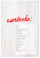
: s t n e cont Specification 4 Location 5 Clearances 6 TV installation above a fireplace 7 Installation guide overview 9 Building the frame 10 Electrical connection 10 Bracket installation 10 Fixing the unit to the frame 11 Flue installation - Rinnai flue kits 12 RDV3611 horizontal flue kits 13 RDV3611 flue components 14 Flue guidelines 16 RDV3611 flueing options 17 Gas connection 18 Flue restrictor installation 19 Log set installat
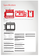
Specification All dimensions are in mm. 995 890 149 750 775 845 510 310 500 400 1090 715 1060 Cover panel Covers 150 mm opening on both sides of the heater. Covers are removed only when a Symmetry Heat Transfer Kit is installed. Outer frame 538 643 1006ID 1110 Symmetry RDV3611 Specification summary Input = 19-33 MJ/h Output = 3.8-7.
Location The main points governing location are flueing and warm air distribution. The heater must not be installed where curtains or other combustible materials could come into contact with the appliance. In some cases curtains may need restraining. Enclosure dimensions The heater must be positioned on a flat level surface. For installations further up the wall, the heater needs to be supported, either construct a base using board, or support with joists. 850 mm min.
Clearances The appliance must not be installed where curtains or other combustible materials could come into contact with the heater. In some case curtains may need restraining. The clearances listed below are minimum clearances unless otherwise stated. Due to the number of different sized Symmetry frames, all dimensions are taken from the edge of the glass.
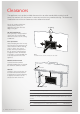
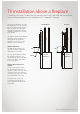
TV installation above a fireplace If installing a flat screen TV above the fire, the main issue is heat. Heat from the fire, and heat from the flueing components that sit behind the TV—especially if recessed Directly Above 75 For a TV mounted directly above the Symmetry RDV3611, the mantel must be at least the depth of the TV to deflect heat away from the appliance. 20 TV Flue TV The diagram shows recommended clearances when installing a TV directly above the Symmetry RDV3611, or into a recess.
Symmetry RDV3611 Installation
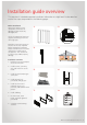
Installation guide overview This overview is intended to provide installation information at a high level. Further detail on each of the steps are provided in the following pages. Before installation Unpack the appliance and components, and check for damage. DO NOT install any damaged parts. 1. 2. 3. 4. 5. 6. 7. 8. Check all components have been supplied, and that you have the correct gas type. Read these instructions to get an overview of the steps required before starting the installation.
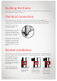
Building the frame Using the dimension information on page 5, construct the frame. Ensure a 25 mm clearance around the sides and back of the unit. Electrical connection The standard electrical connection is to the right side of the front of the appliance. If necessary this can be changed by an electrician to terminate on the left. The appliance must not be located immediately below a socket outlet as this could be a potential fire hazard. 0m 25 A 1500 mm power cord is supplied with a 3-pin plug.
Fixing the unit to the frame The Symmetry RDV3611 comes pre-assembled with the burner already in position. For all installations, the unit MUST BE positioned on a level surface. 1. Position the unit inside the cavity. 2. Bend and secure the two metal standoffs supplied with the unit into position. These provide the required 150 mm vertical clearance to the upper lintel. 3. Fix the unit to the frame with the four mounting brackets.
Flue installation: Rinnai flue kits Rinnai Symmetry RDV3611 flue kits have been based on the flue configurations shown. If you have a combined vertical and horizontal flue configuration, you can order separate components to suit. Roof cowl (high wind) Flue pipe short (1 x 300 mm) or Flue pipe long (2 x 230 mm) Wall terminal (square) Flashing collar Flashing box 90 ° elbow Horizontal flashing kit Flue pipe 900 mm Wall strap Flue pipe 1.
RDV3611 horizontal flue kits The following diagram explains the components, dimensions (mm), and appropriate flue kits available for differing horizontal flue installations. Refer to the table below to calculate what flue pipe length and/or kit you may need.
RDV3611 flue components 108 108 165 165 Flue elbow 90 ° Flue elbow 45 ° Flue pipes Code Code Codes 150 mm 230 mm 300 mm 450 mm 600 mm 900 mm 1200 mm = R3643 Used to facilitate vertical and horizontal flueing. Elbow swivels 360 ° at base. Angle not adjustable. Once joined effective length reduces 35 mm. • 90 ° = 130 mm = R3642 Offsets obstructions. Elbow swivels 360 ° at base. Angle not adjustable. Kit contains two 45 ° bends. Once joined effective length reduces 35 mm.
245.6 mm 325.6 mm Ø268 mm Elbow strap Roof cowl Horizontal flashing kit Code Code Code = R3644 Aluminium flue terminal required for all vertical installations. 338 mm = R3646 Flashing components used to join internal flue to the outside flue, to provide a weathertight seal, in horizontal flue installations. 4 350 mm 338 mm Used to prevent excessive weight in the flue elbow.
Flue guidelines Every gas fireplace requires a flue system that will draw effectively and clear flue products safely under all potential wind and climatic conditions. It is the responsibility of the installer to ensure that the appliance is provided with an effective flue. Some guidelines to assist with flue design are listed below.
RDV3611 flueing options Vertical termination with 45 ° bends Vertical termination with 90 ° bends Horizontal termination with a 90 ° bend Max. 1.2 m Max. 5.4m Max. 5.4 m Max. 5.4 m Ma x. H oriz Restrictor position # 2 ont al = Restrictor position # 3 Restrictor position # 2 (6.0 3-V ertic al)/0 .52 4.2 m 4.2 m 4.2 m Restrictor position # 3 Restrictor position # 4 Restrictor position # 3 3.0 m 3.0 m Restrictor position # 4 Restrictor position # 4 2.4 m 1.
Gas connection The gas connection from the control valve is a ½ “ BSP male flare fitting. This connects straight into the gas control on the lower left hand side of the appliance. Gas pipe sizing must consider the gas input to this appliance, as well as other gas appliances in the premises. 60 CL 190 440 Flared Union To access the gas connection, remove the upper and lower bracket (also called the service access panels). The brackets can be removed by undoing the screws shown below at each end.
Flue restrictor installation Different flue configurations require different positioning of the flue restrictor—refer to the RDV3611 flueing options page to determine what setting is required. The flue restrictor works by limiting the amount of air required for combustion. The higher the flue, the more the air is circulated. This can affect the performance of the fire. The different hole positions are shown in the diagram. These are stamped on the flue restrictor.
Log set installation The log set (burn media) is packaged separately and consists of five log pieces and three moulded rocks. Handle the log set with care to avoid chipping. It is important you position the pieces as shown below as incorrect placement can create carbon build up and affect performance. Malfunctioning due to improper log and rock placement is not covered under warranty. The unit must NEVER be used with broken logs, or used with other burn media, except Rinnai Rockwool.
1. Carefully remove log set from packaging and fit the Front Base Left Log in the created gap. It should only fit one way. 2. Fit Front Base Right Log into position on the far right of the burner base. 1. 2. 3. Fit Front Middle Left Log into the back flat section of the burner, and slot on top of the Front Base Left Log. 4. Place Front Middle Right Log into the u-shaped groove. 5. Place the Top Log onto the recessed sections of the left and right middle logs.
Test pressures To check and set the burner pressures 1. Turn on the gas and power supply to the unit. 2. Refer to the data plate for applicable test point pressures. Outlet test point Inlet test point Cap Gas outlet 3. The test point is on the gas control valve. Using a suitable screw driver loosen the captivated test point screw and attach a manometer. 4. Using the manual control switch (on the appliance), turn the unit on and switch to the HIGH setting, and adjust the pressure as necessary. 5.
Flame pattern It may take approximately two hours of operation for the logs to achieve their full flame pattern and glow. During the initial burning in period, some smoke and smell may be experienced. The appliance should run on the high setting in a well ventilated room until these dissipate. It is important to check the flame pattern during this time.
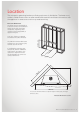
Cladding Cladding MUST NOT extend lower than the cladding support bracket. WARNING Enclosure framework 1120 Cladding Cladding support bracket Front of heater Cladding 150 Cladding support bracket Front of heater When installing the cladding, ensure it is installed up to the flange and not over it. Any overhang will affect performance of the appliance and cause an unsafe situation.
Fitting the frames & dress guard WARNING Before fitting the frames and/or dress guard, ensure the glass front is secured in place. It is critical when fitting the glass front that you double check that it is not scratched or damaged in any way, and that you have checked the gasket. Inner frame Hook over the glass and secure in place on the two large lower magnets on the front assembly. Outer frame Screw into position with the four screws provided.
Wiring diagram (11652-A) AC 230V -240V 50 Hz ACTIVE NEUTRAL OH SWITCH (BROWN) (GREEN) IGNITION PACK 579 DBC SIT Sparker Earth Modulating Coil (Gas Control) (BROWN) Flame Rod Sparker (RED) (YELLOW) FLAME ROD TEST CONNECTION (BROWNN) 1 2 (YELLOW) (GREY) (YELLOW) (GREY) (BLUE) (BLACK) (WHITE) High Speed Medium Speed CONTROL PANEL RECEIVER CABLE CAT 5 FAN MOTOR (BROWN) (GRN/YLW) (BLACK) FUSE 3A 250V (RED) 1 (BLUE) (BROWN) (BLUE) (RED) 2 (BLACK) 12 11 10 9 8 7 6 5 4 3 2 1 (GRN/Y
Rinnai.co.