SYMMETRY® / " 0 ( 0 1$ 123 4 !25 3&! !25 3&! This appliance shall be installed in accordance with: ! " # $ % # " # &' $$ ( ) #* + # # $ # ), ' # - . All Rinnai gas products are A.G.A. certified.
INSTALLATION REQUIREMENTS This heater must be installed by an authorised person. The installation must conform to local regulations. The installation must also comply with the instructions supplied by Rinnai. Service and removal must be carried out by an authorised person. DO NOT modify this appliance. CERTIFICATION The Rinnai Symmetry® has been certified by the Australian Gas Association. The AGA Certification Number is shown on the appliance dataplate.
TABLE OF CONTENTS - OPERATION INSTALLATION REQUIREMENTS ..............................................................................i CARTON CONTENTS ..................................................................................................i CERTIFICATION ..........................................................................................................i INSTALLATION RECORD ..........................................................................................1 ABOUT YOUR HEATER ........
INSTALLATION RECORD INSTALLERS / GAS FITTERS DETAILS Installers Name: _____________________________________________________ Company Name: _____________________________________________________ Company Address: _____________________________________________________ _____________________________________________________ _____________________________________________________ Company Contact Details Telephone: _____________________________________________________ Mobile Phone: _____________________________
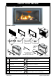
ABOUT YOUR HEATER RDV3610ETR / RDV3611ETR FRONT LAYOUT 12 1 2 10 3 4 4 4 5 9 RDV3610ETR RDV3611ETR 11 8 Typical 2 places 12 6 Note: Cladding support bracket fitted to RDV3611ETR models Only! 7 4 RJ45 Connector Unit Features 1 Mesh Dress Guard 7 Manual Control Switch Panel 2 Mesh Dress Guard Frame 8 Lintel Stand-Off Brackets 3 Surround 9 Red LED Power Indicator 4 Manual Control Panel 10 Remote Sensor Receiver 5 Glass Panel Assembly 11 ‘ON’ / ‘OFF’ Button 6 Lower Horizont
SAFETY • Failure to comply with these instructions could result in a fire or explosion, which could cause serious injury, death or property damage. WARNING • Improper installation, adjustments, service or maintenance can cause serious injury, death or property damage. Such work must be performed by an authorised person. • The appliance must be installed in accordance with the local gas and electrical authority regulations. • Flue terminal must always vent directly to outdoors.
SAFETY WARNING • If the supply cord is damaged or requires replacing, it must be replaced by the manufacturer or the manufacturer's agent or similarly qualified person in order to avoid a hazard. • Heater must not be located immediately below a power socket outlet. • DO NOT connect to an LPG Gas cylinder indoors. • A dedicated 240 V earthed 10 Amp power point must be used with this appliance. • The appliance is not intended for use by young children or infirm persons without supervision.
SAFETY The appliance is not intended for use by young children or infirm persons without supervision. Young children should always be supervised to ensure that they DO NOT play with the appliance. DO NOT allow children or elderly persons to sleep in the warm air discharge from the heater. DO NOT sit or lean against the heater. DO NOT post or allow children to post articles into the louvres of the heater. DO NOT cover or place articles on this heater. DO NOT place articles in front of the louvres.
SAFETY A dedicated 240V earthed 10 Amp power point must be used with this appliance. DO NOT use power boards or double adaptors to operate this appliance. Heater MUST NOT be located below a power socket-outlet. DO NOT place containers of liquid on top of the heater. Water spillage can cause extensive damage to the appliance and create an electrocution hazard. DO NOT place articles on or against this appliance. Turn the heater ‘OFF’ after use.
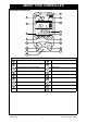
ABOUT YOUR CONTROLLER CONTROLLER DISPLAY 5 3 6 17 4 1 2 7 8 9 10 11 UP A/M OK T 13 P PWR 12 DOWN 14 16 15 LCD DISPLAY 1 2 3 4 5 6 7 8 Time of day with ‘AM’ or ‘PM’ display 9 Day of the week 10 Current Room temperature display 11 Setting Temperature with ‘SET’ display 12 Transmit indicator 13 Battery Low indicator 14 Automatic mode indicator 15 Program mode indicator 16 17 Rinnai Australia 7 Manual mode indicator Setting ‘UP’ Button ‘OK’ Button ‘PWR’ (Power) Button ‘A/
REMOTE / THERMOSTAT CONTROL BUTTON AND DISPLAY FEATURES Item 1 Time of day Feature / Function 2 Day of week 3 Current room temperature display 4 Setting temperature display 5 Transmit indicator Indicates that the thermostat is transmitting to the receiver, the symbol will appear on the LCD for 1 sec. 6 Battery low indicator Indicates when the battery power is below an acceptable level.
REMOTE / THERMOSTAT CONTROL REMOTE CONTROLLER - INITIAL SET UP Before you start Carefully remove the battery compartment cover panel from the rear of your controller hand-set and correctly insert the two AA batteries supplied ensuring '+' and '-' polarity is correct. When installing your batteries your remote control will display the 'Initial Set-up Screen'. The screen will display the following: • Current room temperature in Deg.
REMOTE / THERMOSTAT CONTROL WIRELESS CONTROLLER THERMOSTAT The wireless controller is designed to be wall mounted on a bracket, (bracket supplied with the controller), within 20 m of the heater. The controller houses the thermostat which senses room temperature and communicates back to the Symmetry® via Radio Frequency. The ideal position for the controller is: • Away from possible drafts in the room. • Away from direct sunlight. • Suitable distance away from the heater. • Ideally 1.
CUSTOMER INFORMATION - OPERATION MODES OF OPERATION TO TURN REMOTE ‘ON’ or ‘OFF’ • To turn ‘ON’ - press and release the ‘OK’ and ‘PWR’ Buttons at the same time, display will now include the setting temperature and the mode of operation. • To turn ‘OFF’ - press the ‘PWR’ Button only. MANUAL TEMPERATURE MODE • Temperature can be set at any level. • Time and day of week does not need to be programmed to operate.
HOW TO OPERATE YOUR HEATER FLASHING SMALL FLAME SYMBOL ‘ON’ The small flashing flame symbol on the RF controller display indicates the room temperature is within 0.5°C of set temperature. TO BEGIN PROGRAMMING With the controller ‘OFF’, press and hold the ‘P’ button for 2 seconds to initiate programming. The LCD will display ‘PROG’. ‘Pd’ and the time at which the controller is currently set will flash. Period 1 can now be set. Setting the day of the week (days of the week flash) Step 1.
HOW TO OPERATE YOUR HEATER The controller is factory set, therefore synchronise will not be necessary, however if you have purchased the controller as a spare part then refer to the following. NOTE Initial setup, synchronising the controller to your Symmetry heater, required only if the controller is purchased as a spare or replacement part. Before proceeding with synchronisation ensure that the gas and electricity are connected.
HOW TO OPERATE YOUR HEATER MANUAL SWITCH MODE 10 If you lose your remote controller or the batteries go flat you can still operate your unit in * ‘Manual Switch Mode’. Step 1. Press ‘ON’/‘OFF’ button 11 until the sparker can be heard. The button is discretely located on the ‘Manual Control Switch Panel’ at the bottom right of the heater. 9 11 4 Step 2.
CARE AND MAINTENANCE Your heater needs very little maintenance, but the following information will help you to keep it looking good and working efficiently. DO NOT attempt to clean the heater while the appliance is hot or operating. IMPORTANT All parts of the heater can be cleaned using a soft, damp cloth. DO NOT use solvents or abrasives to clean any parts. DO NOT spray aerosols in the vicinity of the heater whilst in operation. DO NOT place articles on or against this heater.
TROUBLE SHOOTING TROUBLE SHOOTING CHECKLIST Not plugged in or turned off Mains power failure (Initial Install) Air in gas pipe Air in hose Ignition failure Flat battery for remote control Gas supply turned off Gas escape Inadequate flue system Insufficient gas pressure Log Misalignment Normal operation Fault Condition Remote not working Glass, Streaky lines Glass, Condensating Severe sooting Minor soot deposits Fan Not Working Probable Cause Smell of gas Fault Condition Burners fail to ignite U
TABLE OF CONTENTS - INSTALLATION SPECIFICATIONS .....................................................................................................18 GENERAL SPECIFICATIONS ...................................................................................................... 18 DIMENSIONS ............................................................................................................19 HEATER LOCATION.............................................................................................
SPECIFICATIONS GENERAL SPECIFICATIONS Model RDV3610ETR / RDV3611ETR Model Name Symmetry® Gas Log Flame Fire Features Balanced Flue Inbuilt Gas Space Heater Burning log effect Glass front Convection Fan, top warm air outlet Wireless Remote control/thermostat, 7 day programmable timer Installation Inbuilt only Combustion Method Ceramic top pan burner - bunsen burner type Flue Balanced Co-Axial Flue, Inner = 100 mm or 4 ‘Outer = 170 mm or 6 x 5/8’, for Flueing configuations refer page 27 Gas connec
DIMENSIONS 310 520 1090 715 MAIN BODY 750 775 149 845 500 400 995 890 1060 14 RDV3611ETR 538 RDV3610ETR 534 RDV3611ETR 643 RDV3610ETR 639 1006ID OUTER SURROUND 1110 Dimension Without Surround (mm) RDV3610ETR / RDV3611ETR Body Glass Front Cavity Width: 1050 910 1110 1100 Height: 750 410 640 845 Depth: 520 5 13 600 Dimension With Surround (mm) Body Model RDV3610 Glass RDV3611 Width: 1110 Height: 750 RDV3610 Front RDV3611 RDV3610 910 534 *Depth RDV3611 1110
HEATER LOCATION LOCATION • When positioning the heater, variables governing the location are Flueing and Warm Air Distribution. • This heater must not be installed where curtains or other combustible materials could come into contact with it. In some cases curtains may need restraining. Refer to page 6 for additional safety consideration. • Mantles and surrounds can be added to compliment the design provided that they conform to the clearances shown in the drawings below.
HEATER LOCATION ELECTRICAL SUPPLY • This heater is supplied with a power cord (length 1500 mm) and three pin plug. The power cord passes through the right hand side panel as shown. Rinnai recommend the heater be plugged into a 240V, 10A earthed power point. The power point must not be above the heater. A suitable means of electric isolation must be provided which is adjacent to the appliance and accessible with the appliance installed, in accordance with AS/NZS 5601.
TV AND ORNAMENTATION WARNING INSTALLATION OF TV OR ORNAMENTATION ABOVE THE HEATER The temperature of the wall surface directly above the appliance is elevated and may discolour paint finishes or distort vinyl wall coverings. For durability of surfaces you should contact the relevant manufacturer for their specification.
FLUE INSTALLATION CONFIGURATION FLUE INSTALLATION For all installations, only “Abey®” Flue components shown in these instructions MUST BE used. This appliance MUST NOT be flued into ‘natural draft’ flue system or terminate into a chimney. All measurements are in (mm) For vertical and vertical offset flue installations a baffle plate will need to be fitted Total Flue length not to exceed 5400 0 50 Only one 90° change of direction allowed on any installation.
FLUE INSTALLATION CONFIGURATION TYPES OF FLUE INSTALLATION The types of suitable flue configurations are shown above. Other flue configurations are not suitable. Suitable flue components are shown below. Other flue components not shown are not suitable. For full details regarding flue assembly and installation refer to the ‘Simpson Duravent’® “DirectVent Pro” Installation Instructions supplied with the flue components.
FLUE INSTALLATION CONFIGURATION FLUE INFORMATION - ABEY® FLUE SYSTEM Pipe length 48 inch - 46DVA-E48 (1200mm) Abey® Order Code: DV902 Pipe length 24 inch - 46DVA-E24 (600mm) Abey® Order Code: DV904 Pipe length 12 inch - 46DVA-12 (300mm) Abey® Order Code: DV906 Pipe length 9 inch - 46DVA-09 (230mm) Abey® Order Code: DV907 Adjustable Pipe Length 11 - 14 inch - DV911B (275 - 375mm) Abey® Order Code: DV911 90° Elbow - 46DVA-E90 Abey® Order Code: DV990G 45° Elbow - 46DVA-E45 Abey® Order Code: DV945G High Wind
HEATER INSTALLATION HEATER INSTALLATION OVERVIEW READ THIS MANUAL THOROUGHLY AND GAIN A FULL UNDERSTANDING OF THE REQUIREMENTS BEFORE UNDERTAKING INSTALLATION. IMPORTANT Step 1). CONSTRUCTING THE FRAME Step 2). UNPACK THE APPLIANCE Step 3). PREPARING THE APPLIANCE FOR INSTALLATION Step 4). INSERT AND FIX THE APPLIANCE TO THE FRAME WORK Step 5). CONNECT FLUE AND INSTALLING THE FLUE RESTRICTOR *Flue restrictor required for vertical and vertical off-set flue installation. Step 6.
HEATER INSTALLATION 2. Remove the Surround 3 , by removing the 2 retaining screws located on the inner left hand and 2 on the inner right hand side. Place it safely aside. 3. Carefully remove the ‘Glass Panel Assembly’ bottom. Carefully place it safely aside. 1 2 , by removing the 4 retaining screws top and 5 3 5 4. Very carefully remove the log set from the combustion chamber taking care not to scrape the lining or to damage the main burner. 5.
HEATER INSTALLATION Step 5. CONNECT FLUE AND INSTALLING THE FLUE RESTRICTOR Connect the Abey® Flue to the flue outlet at the top of the appliance. A flue restrictor is required for Vertical and Vertical Off-set installations. If a flue restrictor is required install as follows: Step 1. Remove the pilot cover panel by tilting up and back and lifting out from its location slots. Step 2).
HEATER INSTALLATION Step 6 . CONNECT THE APPLIANCE TO CONSUMER GAS PIPING The gas inlet connection is located at the bottom front left of the appliance, 1. Remove the brass nut from the 1/2” flared threaded gas inlet located at the bottom left side of the appliance. Refer to ‘front view’ in drawing below, ensure the brass nut supplied is used. 2. Attach the gas supply pipe to the appliance gas inlet and tighten. 3. Leak test the connection.
HEATER INSTALLATION Piece 2. Long curved log. Location on the front left bottom edge and the rear end bottom edge into the burner body recess. Piece 3. Stocky chipped log. Location is flat on the rear bottom edge into the burner and nestles on the top of ‘Piece 1’. Piece 4. Branching Segment. Nestles in ‘U’ shaped groove with a keyed section into the burner, the front rests on ‘Piece 2’ Piece 5. Bowed log. Right and left ends locates in recesses in pieces 2 & 3 consecutively.
HEATER INSTALLATION Step 10. COMMISSION THE APPLIANCE 240 VOLTS, RISK OF ELECTRICAL SHOCK! WARNING When performing the commissioning, the appliance electrical power will need to be connected. Exercise CAUTION as there is potential for electric shock from the exposed wiring and circuitry. DO NOT leave the appliance unattended when power is connected and the panels are removed. Installation and commissioning must be carried out by an Authorised person. Wiring inside this appliance may be at 240V potential.
HEATER INSTALLATION Step 11. REPLACE PANELS When satisfied that the appliance is igniting and operating correctly, replace lower horizontal cover panel and the manual control switch panel in reverse order of ‘Step 3 (5)’ page 26. Step 12. COMPLETE THE CLADDING Fit the remainder of the cladding. For RDV3610ETR ensure non-combustible material is used in the areas depicted in the drawings below.
HEATER INSTALLATION Step 13. FIT THE SURROUND Fit the surround in reverse order to ‘Step 3 (2) page 26. Step 14. REPLACE MESH DRESS GUARD & DRESS GUARD FRAME ASSEMBLY Replace Mesh Dress Guard & Mesh Dress Guard Frame assembly in reverse order of ‘Step 3 (1)’ page 26. The dress guard fitted to this appliance reducing the risk of fire and injury and no part of it should be permanently removed. WARNING For protection of young children or the infirm a secondary guard is required.
WIRING DIAGRAM WIRING DIAGRAM AC 230V -240V 50 Hz ACTIVE NEUTRAL OH SWITCH (BROWN) (GREEN) (GRN/YLW) IGNITION PACK 579 DBC SIT Sparker Earth Modulating Coil (Gas Control) (BROWN) FLAME ROD TEST CONNECTION (BROWNN) 1 2 Flame Rod Sparker (YELLOW) CONTROL PANEL RECEIVER CABLE CAT 5 (GREY) (BLUE) (YELLOW) (WHITE) (GREY) (BROWN) High Speed Medium Speed (BROWN) (BLACK) FAN MOTOR (RED) 1 FUSE 3A 250V (RED) 2 (BLUE) (BROWN) (BLUE) (BLACK) 12 11 10 9 8 7 6 5 4 3 2 1 (GRN/YLW) 1 2 (
CHECKLISTS INSTALLATION AND COMMISSIONING CHECKLIST • Complete the Installation Check List and the Installer details below. • Instruct customer on the Symmetry® operation. • Ensure the customer understands the content of this manual. NOTE Advise the customer that during the initial burning period of approximately 2 hours, some smoke and smell may be experienced. During this period the heater should be operated on ‘High’ and the space being heated should be well ventilated.
NOTES Rinnai 36 Installation Manual
CONTACT INFORMATION Australia Pty. Ltd. Internet: www.rinnai.com.au E-mail: enquiry@rinnai.com.au ABN 74 005 138 769 Head Office National Help Lines 10-11 Walker Street, Braeside, Victoria 3195 P.O. Box 460 Tel: (03) 9271 6625 Fax: (03) 9271 6622 Sales & Service Tel: 1300 555 545* Fax: 1300 555 655* *Cost of a local call Higher from mobile or public phones.