
Installation Manual


Rinnai Tankless Rack System (TRS) Installation Manual 41
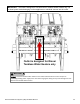
Each Rinnai Tankless Water Heater has a condensate
drain outlet on the boom of the unit. A drain line
must be connected to each water heater.
Free-standing rack systems with 3 or more units will
include a prefabricated condensate manifold. For all
other rack systems, a condensate drain manifold must
be eld-fabricated (not shown in diagram).
Condensate piping must be CPVC or PVC material and
must not be smaller than the drain connecon on the
appliance.
Components of the condensate drainage shall be
CPVC or PVC material. All components must be
selected for the pressure and temperature rang of
the installaon.
Where the drain pipes from more than one unit are
manifolded together for condensate drainage, the
pipe or tubing shall be sized in accordance with an
approved method as dictated by local codes.
Condensate must be disposed of according to local
codes.
The condensate drain pipe (along its enre
length) must be at least the same diameter as the
drain line.
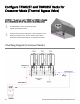
TRS03ILCU TRS03CU TRS04CU
TRS36CU TRS46CU TRS05CU
TRS06CU
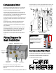
Condensate manifolds are installed above the water
manifolds of the following racks for single point
condensate connecon. Models available with
condensate manifolds include:
Condensate drain must be sloped downward from the rack
system. Condensate must be disposed of per local codes.
Field-supplied
PVC
Condensate Manifold
3/4” Connecon
The telescoping ng on the
capped side of the conden-
sate manifold is for air relief.
DO NOT plug the opening.
NOTICE
Piping Diagram for
Basic Installaon
Condensate Manifold
Condensate Drain
Condensate
Trap Drain
Plug
Pressure Relief Valve
Connecon
Cold Water
Inlet
Condensate
Drain Line
Hot Water
Outlet
Gas
Connecon