Tankless Rack System (TRS) InstallaƟon Manual Additional information can be obtained from the appliance manual. Wall Mounted Rack (4 water heaters) Free Standing Rack (6 water heaters) WARNING If the informaƟon in these instrucƟons is not followed exactly, a fire or explosion may result causing property damage, personal injury or death. — Do not store or use gasoline or other flammable vapors and liquids in the vicinity of this or any other appliance.
Table of Contents Description ............................................................ 3 Parallel Piping Drawing ....................................... 11 Venting Options..................................................... 3 End caps / Connections ...................................... 12 TRS Part Nos. and Main Components.................. 4 Replacement Parts .............................................. 12 Specifications ........................................................
DescripƟon Rinnai Tankless Rack Systems (TRS) include wall mounted and free standing configura ons. The wall mounted rack systems are available for 2, 3, or 4 water heaters. Free standing rack systems are available for 2, 3, 4, 5, or 6 water heaters. The TRS can be ordered with Rinnai’s Common Ven ng System, which consists of the CVent exhaust ven ng and PVC intake ven ng Up to eight tankless units share the same CVent system. The Rinnai TRS features design details that make installa on straigh orward.
TRS Part Nos. and Main Components Part No.
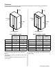
SpecificaƟons Description (2) RU98 Wall Mount (3) RU98 Wall Mount (4) RU98 Wall Mount Top Level Part No. RW2 RW3 RW4 Rack Frame - Specifications Water Heater Model RW2 RW3 RU98i/e N/P 54.81 x 62.00 x 12.75 62 x 75 x 36 63.4 197.1 260.5 142.0 402.5 RW4 Frame (HxLxD) - in Crate Dimensions (HxLxD) - in Weight - Assembly w/o WHs - lbs Weight - Water Heaters - lbs Weight - Fully Assembled - lbs Weight - Packaging - lbs Weight - Shipping (total) - lbs Description Top Level Part No.
SpecificaƟons Description (2, 3, 4) RU98 Wall Mount Top Level Part No.
Clearances Install the rack system so that the clearances shown below (specified for the water heater in the RU98i and RU98e installation manual) are followed.
HoisƟng Lugs are installed on the free standing racks for hoisting and moving. The lines or cables to the lugs should be at a 90° angle. Use a spreader lifting bar to hoist the free standing racks. For wall mounted racks, use hoisting straps looped around the top frame. The weights of the complete assemblies are in the Specifications section. Spreader Lifting Bar DO NOT hoist the crate or palette.
MounƟng Wall Racks 1. Iden fy the installa on loca on and confirm that the installa on will meet all required clearances. 2. Securely a ach the rack to the wall. Ensure that the a achment strength is sufficient to support the weight. Refer to the weight in the Specifica ons sec on. Use a leveling tool to ensure that the water heater is level. Proper opera on requires that the water heater be level. The rack / water heaters should be installed in an upright posi on. Do not install upside down or on its side.
Relief Valve Piping Each Rinnai tankless water heater on the TRS comes installed with Isola on valves and a pressure relief valve. Refer to the installa on and opera on manual for more informa on on proper piping for the relief valve drain. Pressure Relief Valve Isola on Valve Piping for MulƟple Racks Mul ple rack systems should be installed in parallel using a secondary manifold from the building cold and hot water supply. Reference the drawing for guidance.
Rinnai Rack Installation
End Caps / ConnecƟons End caps are to be field supplied and to be of the following materials: • Cold water cap ‐ brass • Hot water cap ‐ brass • Gas cap ‐ black iron Once flow direc on and gas supply side is determined the other (opposite) side of the manifold must be capped. See the example below. Leak check the capped ends of the manifolds. HOT OUT CAP COLD IN CAP CAP GAS IN Replacement Parts If any parts are replaced on the rack, they must be the same or equivalent.
Condensate Drain Checklist for Plumbing Each Rinnai tankless water heater has a condensate drain outlet on the bo om of the unit. A drain line must be connected to each water heater. □ Purge the water line of all debris and air by Condensate Drain Manifold must be field fabricated (not shown in diagram) Condensate piping shall be CPVC or PVC material and shall not be smaller than the drain connec on on the appliance. Components of the condensate drainage shall be CPVC or PVC material.
InstallaƟon of Gas Supply ConnecƟng Electricity WARNING WARNING Do not use an extension cord or an adapter plug with this appliance. 1. If you are not knowledgeable or qualified to install gas lines or connec ons, then contact a licensed professional to install the gas supply. The water heater must be electrically grounded in accordance with local codes and ordinances or, in the absence of local codes, in accordance with the Na onal Electrical Code, ANSI/NFPA No. 70. 2. Turn off 120v power supply. 3.
MSB InstallaƟon Water Heater PC board All of the water heaters should be electronically con‐ nected using the MSB control system. The only excep‐ on is when a water heater is dedicated to recovering a tank. The MSB kits can electronically connect up to 25 water heaters. A M C1 When over 5 water heaters are connected together, MSB‐M units are connected using MSB‐C2 kits. C2 If mul ple MSB‐M are used, then at least three water heaters should be connected to each MSB‐M.
MSB InstallaƟon 1. On the master MSB, one connector is connected to the terminal connector and the other one is con‐ nected to the MSB Communica on cable. Master MSB board 2. When 2 MSB boards are used a MSB Communica‐ on cable will be installed between the master MSB board and the second MSB. The open con‐ nector will have the Terminal connector installed on both MSB boards. 2nd MSB board A maximum of 5 MSB boards can be connected to each other.
Final Checklist □ □ □ □ □ □ □ □ □ □ □ □ □ □ □ □ The water heater is not subject to corrosive compounds in the air. The water supply does not contain chemicals or exceeds total hardness that will damage the heat exchanger. □ Clearances from the water heater unit are met. □ Clearances from the vent termination / air intake are met.
Extended Limited LABOR Warranty* Tankless Rack System REGISTRATION REQUIRED* Rinnai is providing the opportunity to extend your Rinnai Standard Limited Warranty for labor only on the tankless water heater product installed as part of the Tankless Rack System and used in a commercial applicaƟon. You must register the product within 30 days of purchase of the system to qualify.
or damaged during return shipping, the warranty claim for product, parts and labor may be denied. How do I get service? You must contact a licensed professional for the repair of a product under this Limited Warranty. For the name of a li‐ censed professional please contact your place of purchase, visit the Rinnai website (www.rinnai.us), call Rinnai at 1‐800‐621 ‐9419 or write to Rinnai at 103 Interna onal Drive, Peachtree City, Georgia 30269. Proof of purchase is required to obtain warranty service.
100000294 8/2012 Rinnai Rack Installation