
Installation Sheet


13 Rinnai Rack Installation
Condensate Drain
Each Rinnai tankless water heater has a condensate
drain outlet on the boom of the unit. A drain line
must be connected to each water heater.
Condensate Drain Manifold must be field fabricated
(not shown in diagram)
Condensate piping shall be CPVC or PVC material and
shall not be smaller than the drain connecon on the
appliance.
Components of the condensate drainage shall be
CPVC or PVC material. All components shall be
selected for the pressure and temperature rang of
the installaon.
Where the drain pipes from more than one unit are
manifolded together for condensate drainage, the
pipe or tubing shall be sized in accordance with an
approved method as dictated by local codes.
Condensate must be disposed of according to local
codes.
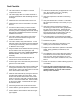
Water
drain plug
Condensate
trap drain plug
Condensate
drain line
Gas
connection
Cold water
inlet
Hot water
outlet
The condensate drain pipe (along its entire
length) must be at least the same diameter
as the drain line.
Piping Diagram for Basic Installaon
Checklist for Plumbing
□ Purge the water line of all debris and air by
closing the hot isolaon valve and opening the
cold isolaon valve and its drain. Debris will
damage the water heater. Use a bucket or hose
if necessary.
□ Ensure that hot and cold water lines are not
crossed to the unit and are leak free.
□ Ensure that a pressure relief valve is installed with
a rang that exceeds the BTU input of the water
heater model. Refer to the rang plate on the
side of the water heater for BTU input.
□ Clean the inlet water filter by closing the cold and
hot water inlet isolaon (shut‐off) valves. Put a
bucket under the filter at the boom of the water
heater to catch any water that is contained inside
the unit. Unscrew the water filter. Rinse the
filter to remove any debris. Install the filter and
open the isolaon valves.
□ Check for proper water pressure to the water
heater. Minimum water pressure is 50 psi. Rinnai
recommends 60‐80 psi for maximum
performance.