
Installation Sheet


16 Rinnai Rack Installation
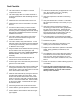
1. On the master MSB, one connector is connected to
the terminal connector and the other one is con‐
nected to the MSB Communicaon cable.
2. When 2 MSB boards are used a MSB Communica‐
on cable will be installed between the master
MSB board and the second MSB. The open con‐
nector will have the Terminal connector installed
on both MSB boards.
A maximum of 5 MSB boards can be connected to each
other. The terminal connector is connected on the ter‐
minal MSB which has an open connector.
NOTE: When viewing the installed MSB board, the dip
switch will be as shown below (upside down).
MSB InstallaƟon
3. Set No 3 switch on the master MSB to ON. The LED light 6
should turn ON confirming the connecon.
4. Set No 4 switch on the second MSB to ON. The LED light 6
should turn ON confirming the connecon.
5. Set No 3 and No 4 switches on the third MSB board to ON. The
LED light 6 should turn ON confirming the connecon.
6. Set the No 5 switch on the fourth MSB board to ON. The LED
light 6 should turn ON confirming the connecon.
7. Set No 3 and No 5 switches on the on the fih MSB board to
ON. The LED light 6 should turn ON confirming the connecon.
Master MSB board
2nd MSB board
2nd to 4th
MSB board
5th or Terminal
MSB board