
Service Manual


4 Rinnai Corporation Conversion Manual
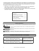
NOTICE
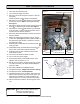
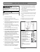
2 machine
screws
(gas valve)
Confirm that the inlet gas pressure is between the minimum and maximum pressures allowed for this appliance.
Gas Conversion Procedure
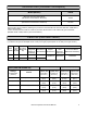
If subsequent conversions are made
then a new conversion label must be
placed on the water heater to
accurately reflect the gas type.
6 screws
(gas
manifold)
Figure 1
1. Disconnect the electrical power.
2. Turn off the gas supply and water.
3. Remove 4 screws securing the front panel. Remove
front panel.
NOTE: Set aside screws in Steps 3-6 separately.
4. Remove the 6 screws that attach the gas manifold
to the burner case on the heat exchanger assembly.
See Figure 1.
5. Remove the display mounting screw and the ignitor unit
screw to replace the gas manifold. See Figure 1.
6. Remove the 2 screws that attach the gas manifold
to the gas valve. These screws are machine screws
and must be used at these locations.
7. Disconnect electrode and flame rod wires and remove
the gas manifold.
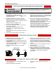
8. Make sure that the black O-Ring is intact on the gas
control valve (see Figure 2) and the gasket is intact on
the replacement gas manifold. Position the new gas
type manifold in place.
9. Install the gas manifold with the 2 machine screws
at the gas valve.
10. Install replacement gas manifold with 6 screws at
burner case on the heat exchanger assembly.
11. Install the ignitor module & bracket screw and the
status monitor screw.
12. Connect the electrode and flame rod wires.
13. Turn on the 120 V power supply.
14. Push and hold PB2 to enter MODE function. LED
displays 1, then changes to A or C.
15. Set the gas type value to the appropriate type A (LPG)
or C (NG). To do this, push PB4 until LED displays A
(LPG) or C (NG).
16. Press and hold PB2 to exit MODE function.
17. Complete the section, Adjust Gas Pressure Settings.
18. Complete the section, Check Operation.
19. Complete the data on the conversion rating plate and
place it on the left side of the unit to cover up the gas
pressures and gas label (on indoor models) for the
other gas type. Do not cover up the Recover Rating.
20. Place the instructions label on the top right side of the
unit.
1 ignitor module and
bracket screw and
1 status monitor screw
O-Ring
Figure 2
Electrode and flame rod wires