
Service Manual


Rinnai Corporation Conversion Manual 5
Adjust Gas Pressure Settings
1. Turn OFF the gas supply.
2. Remove the front panel (four screws).
3. Check the gas type using the new rating label on
the side of the unit.
4. Confirm gas type was selected correctly from the
Gas Conversion Procedure section (steps 14-16).
5. Turn OFF the power supply.
6. Remove the test port sealing screw and attach a
manometer to the burner test point located on the
gas control. Figure 1.
7. Turn on the gas supply and the power supply.
8. If a controller is installed, turn the unit ON and
select maximum delivery temperature.
9. Open all available hot water taps to flow water
through the water heater at the maximum flow rate
obtainable. (At least 3 gallons per minute is
recommended. If there is not enough water
flowing, the water heater could shut off or sustain
damage due to overheating.)
10. To set unit into “Forced Low”, press and hold PB5
until the LED display will show “L”. The front status
monitor will show “FL”. Figure 2
11. Calibrate to Forced Low using PB3 to increase
gas pressure and PB4 to decrease. Figure 2
12. To set unit into “Forced High”, press and hold PB5
until the LED display will show “H”. The front status
monitor will show “FH”. Figure 2
13. Calibrate to Forced High using PB3 to increase
gas pressure and PB4 to decrease. Figure 2
CAUTION
Do not touch the areas at or near the heat exchanger
or hot water lines. These areas become very hot and
could cause burns.
CAUTION
Do not touch any other areas on the PC board
besides the “SW” switches while power is supplied to
the appliance. Parts of the PC board are supplied
with 120 volts AC.
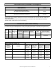
14. Use the Gas Pressure Settings on “Technical
Data” page of this manual for your model, gas
type, and altitude.
15. Return the unit to normal operation by pressing
and holding PB5 until the LED display turns off.
16. Close hot water taps.
17. Turn off both gas supply and 120 V power supply.
18. Remove manometer and install test port sealing
screw.
19. Turn on both the gas supply and 120 V power
supply.
20. Operate the unit and check for gas leaks.
21. Install the front panel using four screws.
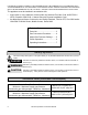
Complete this section for high altitude installation or after converting for gas type.
Confirm that the inlet gas pressure is between the minimum and maximum pressures allowed for this appliance.
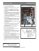
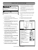
Figure 2
1. Push Buon 2 (PB2) - Black
MODE buon, places the PCB into
programming mode.
2. Push Buon 3 (PB3) - White
MENU buon, cycles through available
menus 1 - 6. Increases gas pressure during
forced mode operaon.
3. Push Buon 4 (PB4) - White
VALUE buon, cycles through available
menu values. Decreases gas pressure dur-
ing forced mode operaon.
4. Push Buon 5 (PB5) - White
Forced High/Low selecon rate seng.
5. LED Digital Display
Displays MENU ( 1, 2, etc.), VALUE ( A, ,
etc.) and Forced Low/High status (
L
or
H
).
6. Dipswitch
By factory default, all switches are in OFF
posion. Used for High Altude adjust-
ment.
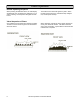
Figure 1
Burner test point
PB2
PB3
PB4
PB5
LED
Dip
Switch