
Installation guide


DM84 Installation Guide
LECTROSONICS, INC.
8
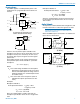
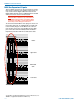
When the DM84 output is connected to a balanced
input, wire it as shown here.
DM Out
+
-
Destination
+
-
DM Out to Balanced Input
(3-Wire)
Shield
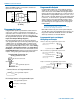
Programmable Inputs
Programmable inputs are provided to enable external
control over a variety of parameters. Each input can
respond to either a contact closure or a continuous volt-
age. The following illustrates common connections to
the programmable input pins. (See also Programmable
Inputs and Outputs Wiring Diagram.)
No external pull-up resistors are necessary because
each programmable input is internally pulled up through
a 100K resistor to +5V. When using a continuous volt-
age with one of the programmable inputs, the function
of the programmable input must be set to either Analog
In Control or Analog Out Control on the Programma-
ble Inputs controltabintheControlPanelGUI.Seethe
Programmable Input tab in the Control Panel software
Help for setting all programmable input parameters.
10K Linear Potentiometer
CCW
CW
+5V
To Programmable Input Pin
Gnd
Contact Closure as Programmable Input
To Programmable Input Pin
Gnd
DC Voltage Source as Programmable Input
To Programmable Input Pin
0VDC (Off) to +5VDC (On)
Gnd
Potentiometer Connection for
Analog Control of Gain
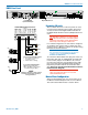
Programmable Outputs
Programmable outputs are used to indicate channel
activity or the current state of a programmable input or
some other feature of the DM84. Each programmable
output is the electrical equivalent of a contact closure to
ground.Whenaprogrammableoutputis“active”,itcon-
ducts current to ground. When the programmable output
is“inactive”,nocurrentowstoground.Themaximum
usable voltage for the programmable outputs is 40 V
and they will safely conduct up to 100 mA DC continu-
ous. Following are some typical uses for the program-
mable outputs.
Note: The diagram shows an external DC
source powering the relay coil. This is necessary
whenever coil voltages exceed 5 V.
Both LEDs and 5V relay coils can be powered by the
+5 V DC pins on the programmable input connector, as
long as the maximum combined current for all LEDS
and relay coils does not exceed 100 mA.
Programmable Inputs and Outputs
Wiring Diagram Example
LED is on when the programmable output is active
380 Ohms
Programmable Output Pin
380 Ohms
LED is off when the programmable output is active
Programmable Output Pin
Gnd (from Programmable I/O
Pins 1, 8, 13)
1N4001
or equiv.
External
DC Voltage
Source
(<40VDC)
Relay Coil
Coil current <100mA
Programmable Output Pin
Gnd (from Programmable I/O
Pins 1, 8, 13)
Relay is on when the programmable output is active
+5VDC (from Programmable I/O
Pins 14, 20, 25)
+5VDC (from Programmable I/O
Pins 14, 20, 25)