FSC-BT986 Datasheet R8002 Bluetooth Module Datasheet Version 1.4 Shenzhen Feasycom Technology Co.,Ltd -1- www.feasycom.
R8002 Datasheet Copyright © 2013-2021 Feasycom Technology. All Rights Reserved. Feasycom Technology reserves the right to make corrections, modifications, and other changes to its products, documentation and services at anytime. Customers should obtain the newest relevant information before placing orders. To minimize customer product risks, customers should provide adequate design and operating safeguards.
FR8002 Datasheet Contents 1. INTRODUCTION ................................................................................................................................................................. 4 2. GENERAL SPECIFICATION ................................................................................................................................................... 5 3. HARDWARE SPECIFICATION ........................................................................................................
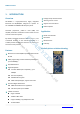
R8002 Datasheet 1. INTRODUCTION Overview Postage stamp sized form factor FSC-BT986 is a high-performance, highly integrated Bluetooth 5.2 BR/EDR/BLE, designed to operate on the 2402MHz to 2480Mhz ISM frequency band. Support Internal Antenna Abundant peripherals, power-on reset (POR) and I2C/USB, arithmetic accelerators further reduce the cost and size of the entire system.
R8002 Datasheet 2. General Specification Table 1: General Specifications Categories Wireless Specification Features Bluetooth Version Implementation Bluetooth v5.2 Dual mode Frequency 2.402 - 2.480 GHz Transmit Power 0 dBm (Maximum) Receive Sensitivity -95 dBm@0.1%BER (BLE mode) Modulation GFSK, π/4 DQPSK, 8DPSK Raw Data Rates (Air) 3 Mbps TX, RX, Supports Automatic Flow Control (CTS and RTS lines).
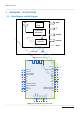
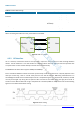
R8002 Datasheet 3. HARDWARE Block Diagram and PIN Diagram ANT UART 24MHZ Crystal I2C 5.2 dual mode BT controller PIO/AIO en Sh ARM USB/LED Cortex-M0 en zh RESET GND om yc as Fe 3.3V~ 3.6V Figure 2: Block Diagram og PIO4 PIO2 PIO3 PIO2 NC RESET NC NC TRAN/USB_DP/PIO1 DISC/USB_DM/PIO0 GND yC 36 35 34 33 32 31 30 29 28 27 26 25 24 23 22 NC GND 14 15 16 17 18 19 20 21 Figure 3: FSC-BT986 PIN Diagram(Top View) -6- d ,Lt o.
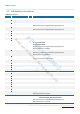
R8002 Datasheet 3.2 PIN Definition Descriptions Table 2: Pin definition Pin Pin Name Type Pin Descriptions 1 UART_TX I/O UART Data output 2 UART_RX I/O UART Data input 3 UART_CTS/PIO6 I/O UART Clear to Send (active low) Alternative Function: Programmable input/output line 4,34 UART_RTS/PIO5 I/O UART Request to Send (active low) Alternative Function: Programmable input/output line I/O Host MCU change UART transmission mode.
R8002 Datasheet 32 PIO4/LED I/O Programmable input/output line Alternative Function: LED(Default) Power On: Light Slow Shinning ; Connected: Steady Lighting. 35 GND Vss Power Ground 36 EXT_ANT O RF signal output . If you need to use an external antenna, you can shield the onboard antenna by modifying the module on the 0R resistor. Or contact Feasycom to modify. 4. PHYSICAL INTERFACE Power Supply en Sh 4.1 en zh The transient response of the regulator is important.
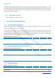
R8002 Datasheet Table 3: Possible UART Settings Parameter Possible Values Baudrate Minimum 1200 baud (≤2%Error) Standard 115200bps(≤1%Error) Maximum 921600bps(≤1%Error) Supports Automatic Flow Control (CTS and RTS lines) Flow control Parity None, Odd or Even Number of stop bits 1 /1.5/2 Bits per channel 5/6/7/8 When connecting the module to a host, please make sure to follow . RX TX Module RTS CTS CTS RTS en GND GND zh en Sh TX RX Host as Fe 4.3.
R8002 Datasheet The device on-chip I2C logic provides the serial interface that meets the I2C bus standard mode specification. The I2C port handles byte transfers autonomously. The I2C H/W interfaces to the I2C bus via two pins: SDA and SCL. Pull up resistor is needed for I2C operation as these are open drain pins. When the I/O pins are used as I2C port, user must set the pins function to I2C in advance. 4.3.3 USB Device Controller USB2.0 fullspeed,4Eps, support host mode. 5. ELECTRICAL CHARACTERISTICS 5.
R8002 Datasheet Out of band emission 2 MHz (GFSK) -40 dBm Out of band emission 3 MHz(GFSK) -48 dBm 20dB bandwidth 0.9 MHz Table 7: BLE Receiver Characteristics Parameter Min Type Max Unit -95 dBm Standard Gain mode, Sensitivity @0.1% -92 dBm Maximum Input Power 0 dBm Co-channel C/I, Basic Rate, GFSK 7 dB ACS C/I 1MHz, Basic Rate, GFSK 5.
R8002 Datasheet 7. RECOMMENDED TEMPERATURE REFLOW PROFILE Prior to any reflow, it is important to ensure the modules were packaged to prevent moisture absorption. New packages contain desiccate (to absorb moisture) and a humidity indicator card to display the level maintained during storage and shipment. If directed to bake units on the card, please check the below next table and follow instructions specified by IPC/JEDEC J-STD-033. Note: The shipping tray cannot be heated above 65°C.
R8002 Datasheet Pre-heat zone (A) — This zone raises the temperature at a controlled rate, typically 0.5 – 2 °C/s. The purpose of this zone is to preheat the PCB board and components to 120 ~ 150 °C. This stage is required to distribute the heat uniformly to the PCB board and completely remove solvent to reduce the heat shock to components.
R8002 Datasheet zh en Sh 2.4mm(Max.) en om yc as Fe Te Host PCB Land Pattern and Antenna Keep-out for FSC-BT986 Please check the picture below for Pad Structure and Keep Out Area: d ,Lt o. 8.
R8002 Datasheet en zh en Sh om yc as Fe l no ch Te Figure 8: Host PCB-Top View yC og Soldering Recommendations d 9.1 ,Lt o. 9. HARDWARE INTEGRATION SUGGESTIONS FSC-BT986 is compatible with industrial standard reflow profile for Pb-free solders. The reflow profile used is dependent on the thermal mass of the entire populated PCB, heat transfer efficiency of the oven and particular type of solder paste used. Consult the datasheet of particular solder paste for profile configurations.
R8002 Datasheet 9.2 Layout Guidelines(Internal Antenna) It is strongly recommended to use good layout practices to ensure proper operation of the module. Placing copper or any metal near antenna deteriorates its operation by having effect on the matching properties. Metal shield around the antenna will prevent the radiation and thus metal case should not be used with the module.
R8002 Datasheet As indicated in below, RF critical circuits of the module should be clearly separated from any digital circuits on the system board. All RF circuits in the module are close to the antenna port. The module, then, should be placed in this way that module digital part towards your digital section of the system PCB.
R8002 Datasheet n et n A PCB Wrong n et n A n te n A PCB PCB Better Best Figure 12: Recommended Trace Connects Antenna and the Module en Sh Routing of the RF-connection underneath the module should be avoided. The distance of the micro strip line to the ground plane on the bottom side of the receiver is very small and has huge tolerances. Therefore, the impedance of this part of the trace cannot be controlled. Use as many vias as possible to connect the ground planes.
R8002 Datasheet zh en Sh en Figure 13: Tray vacuum Fe Packing box(Optional) om yc as 10.2 yC og l no ch Te d ,Lt o.
R8002 Datasheet 11.
FCC warning FCC 15.105 This device complies with part 15 of the FCC Rules. Operation is subject to the following two conditions: (1) This device may not cause harmful interference, and (2) this device must accept any interference received, including interference that may cause undesired operation. Changes or modifications not expressly approved by the party responsible for compliance could void the user's authority to operate the equipment.
This device is intended only for OEM integrators under the following conditions: The module can be used to installation in other host. The antenna(s) used for this transmitter must be installed to the provided separation distance of at least 20cm from all persons and must not be co‐located or operating in conjunction with any other antenna or transmitter.The module shall be only used with the integral antenna(s) that has been originally tested and certified with this module.