
Data Sheet
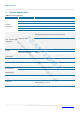
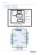
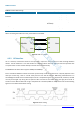
Table Of Contents

R8002 Datasheet
-8
-
32
PIO4/LED
I/O
Programmable input/output line
Alternative Function: LED(Default)
Power On: Light Slow Shinning ; Connected: Steady Lighting.
35 GND Vss Power Ground
36 EXT_ANT O RF signal output .
If you need to use an external antenna, you can shield the onboard
antenna by modifying the module on the 0R resistor. Or contact
Feasycom to modify.
4. PHYSICAL INTERFACE
4.1 Power Supply
The transient response of the regulator is important. If the power rails of the module are supplied from an external
voltage source, the transient response of any regulator used should be 20μs or less. It is essential that the power rail
recovers quickly.
4.2 RF Interface
For this module, the default mode of the antenna is internal antenna.
The user can connect the 50 ohm antenna directly to the RF port.
2402–2480 MHz
TX output power of 0 dBm.
Receiver to achieve maximum sensitivity -95dBm @ 0.1% BLE
4.3 Serial Interfaces
4.3.1 UART
FSC-BT986 provides one channels of Universal Asynchronous Receiver/Transmitters(UART)(Full-duplex asynchronous
communications). The UART Controller performs a serial-to-parallel conversion on data received from the peripheral
and a parallel-to-serial conversion on data transmitted from the CPU. Each UART Controller channel supports ten types
of interrupts.
This is a standard UART interface for communicating with other serial devices. The UART interface provides a simple
mechanism for communicating with other serial devices using the RS232 protocol.
When the module is connected to another digital device, UART_RX and UART_TX transfer data between the two
devices.
This module output is at 3.3V~ 3.6V CMOS logic levels (tracks VCC). Level conversion must be added to interface with
an RS-232 level compliant interface.
Shenzhen Feasycom Technology Co.,Ltd