WOTS WOT - Instructions The Designer Chris Foss outside his factory in 1990 Chris Foss The fascination of flight captured Chris's imagination early on in his life when he started building, from kits and plans, simple free flight gliders and rubber powered models. By his early teens, Chris was already experimenting with his own designs, several of which have been featured as constructional plans in various aeromodelling magazines.
WOTS WOT - Instructions Introduction Congratulations on your purchase of the WOTS WOT ARTF - the first Almost Ready to Fly version of this classic biplane. Designed to be quick to rig at the flying field (and fit in most family cars fully assembled) it can be completed in the minimum of time. Before commencing construction, please ensure that you read these instructions in their entirety.
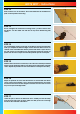
WOTS WOT - Instructions STEP 6 Locate the nylon dowel and epoxy into one wing panel to act as an alignment peg. STEP 7 Check the fit of the joiner in the two wing halves and once happy, mark the centre-line of the joiner. Coat the inside of the corresponding slot in the wing panel and one half of the brace with rapid setting epoxy. Ensure that adequate epoxy is used to fully cover all surfaces. Insert the brace half-way into the wing panel using the centre-line as a guide. Wipe off any excess epoxy.
WOTS WOT - Instructions STEP 12 Now screw the horn to the aileron. The screws thread into the moulded horn plate on the top surface of the wing. STEP 13 Do not overtighten the control horn mounting screws - you don't want to crush the aileron. Turn the model over and trim off any excess thread using side cutters. STEP 14 Use a small length of tape to hold each of the ailerons at their neutral position while you complete the aileron linkages. Ensure that both aileron servos are centred.
WOTS WOT - Instructions STEP 18 Locate the fibreglass aileron link horns. Test fit the horn in its slot on the top surface, noting that the hole is towards the rear of the aileron. Remove and roughen the horn with coarse sandpaper. Epoxy in position with the base of the horn flush with the bottom of the aileron. Completing the Upper Wing STEP 19 Hinge the ailerons using the same method as with the lower wing. Now locate the nylon dowel and epoxy into one wing panel to act as an alignment peg.
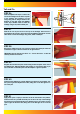
WOTS WOT - Instructions STEP 24 Place the strut mount in position on the wing. Check that you have the correct mounts - the top and bottom are shaped differently to suit the wing curvature. Also check that the mounts are the correct way round by temporarily dry assembling the model with the struts in place to ensure that the are correctly oorientated. Using a sharp knife, carefully trim around the mount's outline as shown.
STEP 30 Using epoxy or canopy glue, fit the canopy using strips of tape to secure while the adhesive cures. Ensure that the canopy is correctly centred front to rear and left to right. Alternatively the canopy can be secured with small screws if preferred. Undercarriage STEP 31 Locate the aluminium main undercarriage, wheels and wheel mounting hardware (axles, collets, washers and nyloc nuts). STEP 32 Insert the axle through the undercarriage leg, fit a washer and tighten the nyloc nut.
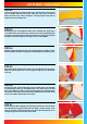
Tail and Fin STEP 36 Slide the tailplane into its pre-cut slot in the rear of the fuselage. Ensure that it is square to the fuselage and centred in its slot using a long ruler or string as shown in the diagram on the right. Mark the tailplane on the top & bottom where it enters the fuselage using a soft, water-soluble pen. = = STEP 37 Slide the fin into its pre-cut slot in the top of the fuselage. Ensure that it is pushed down far enough to touch the top of the tailplane.
WOTS WOT - Instructions STEP 42 Insert two hinges into the rudder and two more in each elevator half, ensuring they are located mid-way in their slots. Using thin cyano, pour a couple of drops onto each hinge - above and below - ensuring the glue soaks into the hinge and the surrounding wood. STEP 43 Protecting the rear of the tailplane with a strip of masking tape, apply epoxy to each half of the wire elevator joiner and force it into the corresponding slots and holes in the elevator halves.
WOTS WOT - Instructions Radio Installation STEP 48 Locate the factory assembled elevator pushrod and slide it into position from the radio bay and out through the exit slot. Screw a nylon clevis onto the rod as shown. STEP 49 Connect the clevis to a control horn and position the horn so that it is in line with the hinge line. Holding the horn in position, pilot drill the elevator for the mounting screws.
WOTS WOT - Instructions Radio Installation STEP 54 With the elevator and servo centred, mark the point that the pushrod passes the servo output arm. Use a wrap of masking tape on the rod to make marking it easier if required. Bend the pushrod up at 90° at this point. STEP 55 Slip the bent pushrod through the servo horn and fit a moulded swing-in keeper. Now trim off the excess length of wire, refit the horn and test the operation of the elevator.
WOTS WOT - Instructions Four Stroke Engine Installation STEP 60 Screw the engine mount onto the bulkhead as shown noting the orientation of the mount. Use the supplied mounting screws and washers using thread locking compound to secure. Note that the captive nuts have already been factory installed in the bulkhead. STEP 61 Place your engine on the mount. Adjust its position until the distance from the front of the prop driver to the front of the main bulkhead (not plywood mount plate) is 127mm.
WOTS WOT - Instructions STEP 66 Install your throttle servo in the precut slot in the radio tray. Adjust the length of the linkage so that mid-throttle stick position corresponds to the carburettor being open 50%. Tighten the screw in the connector and adjust the high and low throttle positions. STEP 67 Connect the fuel line to the engine, pressure to the exhaust (if using exhaust pressure) and block the vent line. STEP 68 Trim the fibreglass cowl to clear the engine and silencer.
WOTS WOT - Instructions STEP 72 With the hatch removed, access to the Li-Po bay is gained. STEP 73 Locate the fixed battery mount. Use a small amount of epoxy to glue the spacer to the end opposite to the bolt hole. STEP 74 Glue the cover plate over the spacer (shown dotted) to form a recess for the tongue of the removable battery tray to locate.
STEP 78 Install your choice of motor to the mounting plate using the screws, washers and nyloc nuts supplied. Screw a threaded stud into the rear of each aluminium stand-off. Now screw the stand-offs to the front former. Use pre-drilled hole in each stand-off for a tommy bar to be used to tighten. Now fit the motor mounting assembly to the stand-offs using the four screws and washers supplied. STEP 79 Mount your ESC as shown to ensure that it gets plenty of cooling air over it.
STEP 84 Now slide on the second wing panel ensuring it butts together to give a gap-free join STEP 85 Tighten the second wing tube retaining screw. Ensure that you do not over-tighten the screws. STEP 86 With the model standing on its nose, connect up the aileron extension leads and locate the lower wing in its seat. Guide the two interplane struts into their strut mounts in the underside of the upper wing. STEP 87 Install and tighten the nylon wing retaining bolts.
WOTS WOT - Instructions STEP 90 Congratulations - your Wots Wot is complete! Do not omit the following steps - checking of the balance point is critical.
WOTS WOT - Instructions Notes: 19
Distributed to your local model shop by: Ltd., 241 Green Street, Enfield, EN3 7SJ.