
User's Manual

The pigmented lens is attached to the inside of the front plastic cover using
a sensor protective sleeve.
1. Remove the sensor protecting sleeve by pushing up the clip that holds
the top part of the sleeve to the front cover.
2. Disconnect the lens from the sleeve by gently lifting it from the holding
pins that secure it to the sides of the sleeve.
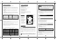
3. Select the desired lens and make sure that the cut corners are pointed
upwards. (Fig. 4).
4. Place the two pins, located on the top and bottom part of the lens, into
the matching holes on the sleeve.
5. Place the holes on either side of the lens into their matching holding pins
on the sides of the sleeve.
6. Insert the protective sleeve back into place on the front cover.
ROKONET LIMITED WARRANTY
Rokonet Electronics, Ltd. and its subsidiaries and affiliates
("Seller") warrants its products to be free from defects in
materials and workmanship under normal use for 24 months
from the date of production. Because Seller does not install
or connect the product and because the product may be
used in conjunction with products not manufactured by the
Seller, Seller can not guarantee the performance of the
security system which uses this product. Sellers obligation
and liability under this warranty is expressly limited to
repairing and replacing, at Sellers option, within a
reasonable time after the date of delivery, any product not
meeting the specifications. Seller makes no other warranty,
expressed or implied, and makes no warranty of
merchantability or of fitness for any particular purpose. In
no case shall seller be liable for any consequential or
incidental damages for breach of this or any other warranty,
expressed or implied, or upon any other basis of liability
whatsoever.
Sellers obligation under this warranty shall not include any
transportation charges or costs of installation or any liability
for direct, indirect, or consequential damages or delay.
Seller does not represent that its product may not be
compromised or circumvented; that the product will prevent
any persona; injury or property loss by burglary, robbery,
fire or otherwise; or that the product will in all cases provide
adequate warning or protection. Buyer understands that a
properly installed and maintained alarm may only reduce
the risk of burglary, robbery or fire without warning, but is
not insurance or a guaranty that such will not occur or that
there will be no personal injury or property loss as a result.
Consequently seller shall have no liability for any personal
injury, property damage or loss based on a claim that the
product fails to give warning. However, if seller is held liable,
whether directly or indirectly, for any loss or damage arising
from under this limited warranty or otherwise, regardless of
cause or origin, sellers maximum liability shall not exceed
the purchase price of the product, which shall be complete
and exclusive remedy against seller.
No employee or representative of Seller is authorized to
change this warranty in any way or grant any other
warranty.
WARNING: This product should be tested at least once a
week.
PROCEDURE FOR CHANGING LENSES
Fig 4.
Lens Change
Procedure
TERMINAL WIRING
STEP 6
Wire cable to the terminal block at the top of the PCB as follows:
12 VDC: Power supply input.
ALARM: Normaly closed output.
TAMPER: Normaly closed dry output.
LEDS: IN - Enables all LEDs
OUT - Disables all LEDs
PULSE: IN - NO Pulse Count (1 pulse)
OUT -Alternative Polarity Pulse Count (2 pulses)
The COSMOS DT has two jumpers that can be either IN (used) or
OUT (unused).
Unused jumpers should be placed on one leg only to prevent their loss.
JUMPER SETTING
STEP 7
WALK TEST
STEP 8
Two minutes after applying power (a warm-up period), walk test the detector
over the entire protected area to verify proper operation of the unit.
The RK-225 needs a longer warm-up period of FOUR minutes. It enables a
powerful long range sensing capability and has increased sensitivity.
Fig 2: Jumper positions.
4
IN
OUT
NOTE
•
Make sure to replace front cover before Walk Test.
•
The MW range can be adjusted using the potentiometer located at the
bottom of the PCB. It is important to set the potentiometer to the lowest
possible setting that will still provide coverage for the entire
protected area.
FINAL SETUP
STEP 9
After completing the installation and testing stages, ensure all jumpers
are at their desired positions. The unit is now ready for normal use.
TOP VIEW SIDE VIEW
Fig 3: Cosmos DT Lenses
5
SPECIFICATIONS
ELECTRICAL
Current consumption: 19mA at 12 VDC
45mA at 16 VDC
(MAX with all LED's ON)
Voltage requirements: 9-16 VDC regulated
Alarm contacts: 24 VDC, 50 mA
Tamper contacts: 24 VDC, 0.1A
OPTICAL
Filtering: White Light Protection
PHYSICAL
Size: 127.6 x 64.2 x 40.9mm
(5 x 2.5 x 1.6 in.)
ENVIRONMENTAL
Operating temperature: -10ºC to 55ºC (14ºF to 131ºF)
Storage Temperature: -20ºC to 60ºC (-4ºF to 140ºF)
1. The models have been listed by Underwriters
Laboratories for use with the wide angle lens
only .
2. The detector is intended to be connected to
a listed burglar alarm control unit capable
of providing 4 hours of standby power.
Specifications are subject to change without prior
notice. Should any questions arise, contact your
distributor.
NOTES FOR UL
6
ROKONET ELECTRONICS LTD.
14 HACHOMA ST.
75655 RISHON LETZION. ISRAEL.
TEL: (972) 3 961 6555 FAX: (972) 3 961 6584
5IN215
© 2001 Rokonet Electronics Ltd
06/01
TEL: 1 914
TEL: 44 (0)
TEL: 33 (0)
TEL: 39 (02)
TEL: 55 (21)
FAX: 1 914
FAX: 44 (0)
FAX: 33 (0)
FAX: 39 (02)
FAX: 55 (21)
ROKONET USA:
ROKONET UK:
ROKONET FRANCE:
ROKONET ITALY:
ROKONET BRAZIL:
592 1068
1527 576 765
155 123390
3925 354
496.3544
592 1271
1527 576 816
148 863042
3925 131
496.3547
COSMOS
DT SERIES
RK-210,215,225
INSTALLATION
INSTRUCTIONS
This equipment has been tested and found to comply with the limits for
a Class B digital device, pursuant to part 15 of the FCC Rules. These limits
are designed to provide reasonable protection against harmful
interference in a residential installation. This equipment generates, uses
and can radiate radio frequency energy and, if not installed and used in
accordance with the instructions, may cause harmful interference to radio
communications. However, there is no guarantee that interference will
not occur in a particular installation. If this equipment does cause harmful
interference to radio or television reception, which can be determined by
turning the equipment on and off, the user is encouraged to try to correct
the interference by one or more of the following measures:
•Reorient or relocate the receiving antenna
•Increase the separation between the equipment and the receiver
•Connect the equipment into an outlet on a circuit different from that to
which the receiver is connected
•Consult the dealer or an experienced radio/TV technician for help.
Changes or modifications to this equipment not expressly approved by
the party responsible for compliance (Rokonet Electronics Ltd.) could
void the user's authority to operate the equipment.
NOTE
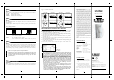
WIDE ANGLE (RL-115)
RK-210/215
CORRIDOR (RL-15)
RK-210/215
2.5m
(8'2")
0.4m
(1'4")
2.5m
(8'2")
10m/15m
(33/49')
1.1m
(3'3")
2.5m
(8'2")
0.4m
(1'4")
2m
(6'7")
5m
(16'5")
10m/15m
(33/49')
WIDE ANGLE
RK-225 RL-125
LONG RANGE
RK-225 (RL-17)
83
3m
2.5m
(8'2")
0.4m
(1'4")
4m
(13'1")
23m
(75'5")
1.1m
(3'3")
2m
(6'7")
0.4m
(1'4")
3m
(9'10")
25m
(82')
1.1m
(3'3")
110
1.3m
/2m
TOP VIEW SIDE VIEW