
User's Manual


WatchOUT DT Relay Mode Installation
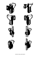
Changing Back Tamper position:
The back tamper is by default secured on the right side of the internal base (Rear
view). If you wish to move it to the left side (rear view), do the following (Figure 5):
1. Remove tamper screw 1 in order to release the tamper from position 7.
2. Ensure tamper spring 2 rests over tamper wire base 4.
3. Ensure plastic tamper bracket 3 rests over both 2 and 4.
4. Secure tamper screw 1 into 3 over position 6.
Notes:
1. Verify that you hear a "Click" when attaching the tamper spring to the wall
2. For pole installation the tamper can be moved to the bottom right-hand side of the internal base.
Figure 5:
Left Side
Tamper
Right Side
Tamper
1
3
6
7
5
4
2
Terminal Wiring
+ -
SET/
UNSET
LEDs
ENABL
AM
YEL
FREE
ALARM TAMPER
GREEN
FREE
DUST TEST
12VDC
N.C
N.C
WatchOUT DT - PCB
+,-
12 VDC
ALARM
N.C relay, 24VDC , 0.1A
FREE
YEL
This terminal is a free pin that can be used to connect
wires and EOL resistors
TAMPER
N.C relay, 24VDC , 0.1A
FREE
GREEN
This terminal is a free pin that can be used to connect
wires and EOL resistors
AM
Normally closed AM relay output (24VDC, 0.1A)
indicates Anti Masking alarm or any trouble in the
detector (Not including dust/ dirty lens).
Note:
When a vibration detector is installed and DP8 is defined as
Enabled this relay also opens momentarily when vibration
event occurs
LED
ENABL E
Used to remotely control the LEDs when DIP1 is set to
ON.
Enable: input is +12V OR no terminal connection
Disable: Connect the input to 0V
DUST N.O. collector max 70 mA. Indicates that the lens is dirty
and requires cleaning.
TEST
Used to perform remote alarm testing to the detector by
applying 0 volts to this terminal.
Success: Alarm relay is momentary opened.
Failure: AM relay is opened
SET/
UNSET
This input enables to control Anti-masking and LEDs
operation in accordance to the system status, Set (Arm) /
Unset (Disarm).
While the system is armed this feature prevents an
intruder from gaining knowledge of the detector’s status
and disables Anti-masking detection.
System
Status
Input
Status
AM
Relay
LEDs
Set (Arm) 0V Off Off
Unset
(Disarm)
12V or no
connection
On* On**
* DIP7 is ON (Anti masking enabled)
** DIP1 is ON (LEDs enabled) and LEDs ENABLE input terminal is
enabled (+12V OR no terminal connection)
Dip switch Settings
1 2 3 4 5 6 7 8
ON
Factory
Default
DIP 1: LEDs operation
On: LEDs enabled
Off: LEDs disabled
DIP 2-3: Detection Sensitivity
Sensitivity DIP2 DIP3
Low Off Off
Mid Off On
Normal
(Default)
On Off
Maximum* On On
* In maximum sensitivity sway
recognition is disabled to achieve
maximum sensitivity
DIP 4: Alarm condition
On: PIR or MW
Off: PIR + MW
DIP 5: Detector's optics
On: Barrier / Long range
Off: Wide angle
DIP 6: Red LED /3 LED
On: Red LED only
Off: 3 LEDs
DIP 7: Anti masking operation
On: Enabled
Off: Disabled
DIP 8: Vibration detection (Only
when the vibration sensor is
installed)
On: Enabled
Off: Disabled
Microwave Adjustment Walk test
Adjust Microwave coverage area by
using the trimmer on the PCB
MIN MAX
Two minutes after applying power, walk test the protected area to verify
proper operation.
For installations on uneven surfaces slide the PCB inside the internal
base to the appropriate setting according to the desired height (1.0m,
1.5m, 2.2m, 2.7m) as printed on the bottom left corner of the PCB or
use the standard swivel accessory.
For reducing the detection range slide the PCB up or tilt the swivel
down.
1.00M
1.50M
2.20M
2.70M
PCB
LEDs Display Relay Mode / Bus Mode Jumper
LED State Description
Steady Indicates PIR detection
YELLOW
Flashing Indicates AM (Anti mask) detection
GREEN
Steady Indicates MW detection
Steady Indicates ALARM
RED
Flashing Indicates malfunctioned communication
with ProSYS (BUS mode only)
All LEDs
Flashing (One
after another)
Unit initialization on power up.
Notes:
1. DIP-Switch 1 should be in ON
position to enable LED indications.
2. Only one LED is active at any
one time. For example, in the case
of both PIR and MW detection,
either the steady YELLOW LED or
the steady GREEN LED is
displayed (the first to detect),
followed by the Alarm RED LED
J-BUS jumper (located on the
PCB between the red and green
LEDs) is used to define the
detector’s mode of operation as
follows:
Relay
Mode
BUS
Mode