
User's Manual


WatchOUT DT Relay Mode Installation
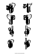
Standard Swivel Installation
The Outdoor detector packaging contains a standard swivel for
flexible installation. Please follow the instructions below for
mounting the detector with the Standard Swivel
1. Open Watc hOUT front cover. (Unlock C1, figure 1).
2. Release internal base (Unlock I1, figure 2).
3. Open knockouts on external base (figure 6)
Ø W1: Wires knockout
Ø S1,S2: Knockouts for securing external base to Standard
Swivel
Ø S3: External base locking screw knockout
4. On the swivel accessory remove the required swivel cable
wiring knockout S2, S7 or S9 (Figure 7)
5. Remove back tamper from the internal base and connect it to
S5 (figure 7) on the Standard Swivel. (See “Changing Back
Tamper Position").
6. Select the mounting installation as follows:
Note:
Ensure that you see the engraved UP mark on the upper front face of
the swivel.
Wall Mounting:
a. Insert external cable wiring through knockouts S2, S7 or
S9 and extract them (including the tamper wires) through
the Swivel Wires Passage (figure 8)
b. Secure swivel to the wall through holes S1, S3, S6 and S8.
Swivel Conduit Mounting (using Conduit Metal Swivel Adaptor –
CSMA, figure 7)
Note:
The CSMA is required when wiring is in a pipe external to the wall. It
should be ordered separately P/N RA300SC0000A.
a. Choose the direction upon which to mount the CSMA
according to the required diameter: 16mm (0.63 inches)
or 21mm (0.83 inches).
b. Insert conduit to the CSMA.
c. Secure CSMA to the wall through points (M1, M4)
d. Insert external cables and tamper wires from the conduit through the
Swivel Wires Passage of the swivel (figure 8)
e. Secure swivel to the wall through holes S1, S3, S6 and S8.
Note:
The Tamper spring S5 (figure 7) should make contact with the wall through the
tamper spring holes M2 or M3 on the CSMA. Make sure to hear the tamper
"Click" when connecting to the wall
7. Insert tamper wires and external cable wiring from Standard Swivel
through knockout W1 on the external base (figure 8)
8. Secure external base to swivel with two screws fastened to knockouts
S1 and S2 (figure 8)
9. On the PCB, lift the black foam below the RED LED and remove angle
locking screw knockout on the internal base (Figure 9)
10. Line up the internal base onto the external base. Insert all wiring cables
through the internal base.
11. Insert the supplied angle locking screw from the PCB (lift the black foam
below the RED LED), through the angle locking screw knockout on the
internal base, through the knockout S3 on the external base to the
standard swivel (figure 8)
12. Tilt and Rotate the Standard Swivel to the desired position. Once the
Standard Swivel is in the desired position, secure the angle locking
screw
Note:
When the marks on the two movable parts are aligned (figure 8), the Standard
Swivel is in the horizontal position at 0?. Each vertical click from this position
represents an increment / decrement of 5?.
13. Secure internal base to external base (Lock I1, figure 2)
14. Close the front cover (Lock C1, figure 1) and walk test the detector
Figure 6:
W1
S1
S2
S3
Figure 7:
21 mm
16 mm
Tamper Spring
Holes
CSMA
M1
M2
M3
M4
Tamper
Swivel Wires
Passage
S1
S2
S3
S4
S5
S6
S7
S8
S9
Figure 8:
S1
S10
External
Base
Internal
Base
PCB
S3
Notes::
1. Do not open or close the Swivel Connecting
Screw since it is used for connecting the swivel parts only.
2. The screw has to pass throug the PCB, the Internal Base, Knockout S3 on the External
Base and locked to the swivel.
Swivel Connecting
Screw (See Note1)
S2
Angle Locking Screw
(See Note 2)
Figure 9:
Angle Locking
Screw Knockout