
Instruction Manual


0830
21-8165 10-11 NCD-5994-7
INSTALLATION INSTRUCTIONS
Congratulations—your new Air Helper Springs are quality
products capable of improving the handling and comfort
of your vehicle. As with all products, proper installation is
the key to obtaining all of the benefits your kit is capable
of delivering. Please take a few minutes to read through
the instructions to identify the components and learn
where and how they are used. It is a good idea to start by
comparing the parts in your kit with the parts list below.
The heart of the Air Helper Spring kit is, of course,
the air helper springs. Remember that the air helper
springs must flex and expand during operation, so be
sure that there is enough clearance to do so without
rubbing against any other part of the vehicle.
Be sure to take all applicable safety precautions
during the installation of the kit. The instructions listed
in this brochure and the illustrations all show the left,
or driver’s side of the vehicle. To install the right side
assembly simply follow the same procedures.
This kit includes inflation valves and air lines for
each air spring. This will allow you to compensate for
unbalanced loads. If you would rather have a single infla-
tion valve system to provide equal pressure to both air
springs, your dealer can supply the optional "T" fitting.
IMPORTANT!
For your safety and to prevent possible damage
to your vehicle, do not exceed the maximum load
recommended by the vehicle manufacturer (GVWR).
Although your Air Helper Springs are rated at a maximum
inflation pressure of 100 psi, this pressure may allow you
to carry too great a load on some vehicles. It is best to
have your vehicle weighed once it is completely loaded
and compare that weight to the maximum allowed. Check
your vehicle owner’s manual or data plate on driver's side
door for maximum loads listed for your vehicle.
When inflating your Air Helper Springs, add air pres-
sure in small quantities, checking pressure frequently
during inflation. The air spring requires much less air
volume than a tire and, therefore, inflates much quicker.
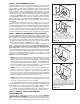
NOTE:
This kit will fit several different van models. From Fig-
ures “B” & “C”, identify the jounce bumper setup
your vehicle has. Follow the corresponding instruc-
tions to remove the jounce bumper. If the jounce
bumper is bolted to the bottom of the frame, remove
the bolts and discard the jounce bumper.
STEP 1 — PREPARE THE VEHICLE
Remove the negative battery cable. Remove the jounce
bumper as noted see Figures “B” & “C”. With the vehicle
on a solid, level surface, chock the right-side wheels.
Raise the left side of the vehicle by the frame and remove
the left rear wheel. After the removal of the wheel, lower
the vehicle so the frame rests on jack stands rated for
your vehicles weight. Adjust the jack stands so that the
vehicle is held as high as possible.
WARNING:
Do not inflate this assembly when it is
unrestricted. The assembly must be
restricted by the suspension or other
adequate structure. Once installed, do not
inflate beyond 100 psi. Improper use or over
inflation may cause property damage or
severe personal injury.
AIR SPRING 6859 2
UPPER BRACKET 0828 2
ANGLED ADAPTER 0861 2
UPPER BRACKET BRACE 0821 2
SLEEVE – 3-1/2" 0823 4
SLEEVE – 3/8" 0941 4
90 DEGREE ADAPTER 0921 2
LOWER BRACKET 1162 2
AXLE STRAP 5077 4
AIR LINE TUBING 1
PUSH-TO-CONNECT INFLATION VALVE 2
PUSH-TO-CONNECT ELBOW FITTING 2
HEAT SHIELD 1
3/8" -16 X 3/4" HEX BOLT 6
3/8" -24 X 2-1/2" RIBBED NECK BOLT 8
3/8" -16 HEX NUT 4
3/8" -24 HEX NUT 10
3/8" FLAT WASHER 2
1/4" X 20 X 4-1/2" HEX BOLT 4
1/4" -20 HEX NUT 4
1/4" LOCK WASHER 4
1/4" FLAT WASHER 8
5/16" FLAT WASHER 4
NYLON TIE 6
THERMAL SLEEVE 2
CAUTION TAG 2
PARTS LIST