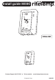
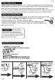
Install guide 8035C MENU PROG RESET ENGLISH MENU PROG RESET Customer Support: 888-515-2585 or Visit our website Printed in China www.ritetemp-thermostats.
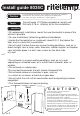
Install guide 8035C Caution To avoid electrical shock and to prevent damage to the furnace, air conditioner, and thermostat, disconnect the power supply before beginning work. This can be done at the circuit breaker, or at the appliance. Tools You will need #1 Phillips screwdriver (small) and Drill with 3/16-in. (4.8mm) bit for this installation. 1 Location PG 1 ï On replacement installations, mount the new thermostat in place of the old one if possible.
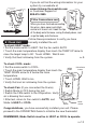
2 Remove old unit PG ï Switch electricity to the furnace and air conditioner OFF; then proceed with the following steps. ï Remove cover from old thermostat. Most are snap-on types and simply pull off. Some have locking screws on the side or front. These must be loosened. Note the letters printed near the terminals. ï Attach labels (enclosed) to each wire for identification. Read instructions carefully before removing any wiring from existing thermostat. Wires must be labeled before they are removed.
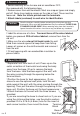
PG 4 Gas-Electric Selection 5 Rear View of control unit REFER to the back of the Control Unit: ï If you have Electric Heat or a Heat Pump (without auxiliary heat) you must place the Gas/Electric jumper in the ELECT position (thermostat controls the Fan). ï If you have Gas Heat the Gas/Electric Jumper should be in the GAS position (furnace controls the Fan ). GAS ELECT 5 Install Batteries The 8035C requires batteries to operate your furnace and retain its programming in memory.
PG 7 7 Wire Connections Make sure your wires are labeled. This is necessary to determine which step-by-step wiring diagram you should use. This may require you to find the 'other end' connection for each wire on your heating or air conditioning equipment and read the label there. If you have a Zoned Heating/Cooling system with multiple thermostats, please refer to our website at www.ritetemp-thermostats.com for installation notes or call 1-888-515-2585.
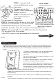
pump From heat at w/o Aux he Y O or B G C R Go To Page 15 If you do not find the wiring information for your system try our website at www.ritetemp-thermostats.com or Customer Support at 888-515-2585 MENU PROG 7 Wire Connections cont When you have finished connecting the wires, close cover and attach control unit to wall unit. Hook the top of the body onto the base, swing the body down, and snap the body onto the base.
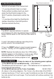
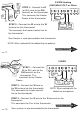
ce From Furna C R or RH W 2 WIRE Heating (GAS MILLIVOLT or 24vac STEP 1 - Connect the R (or RH) wire to the RH terminal on the thermostat. This connects the Heater Power to the thermostat. Thermostat A jumper wire C STEP 2 - Connect the W wire to the W terminal on the thermostat. This connects the heater control line to the thermostat. R W HEAT Power HEAT FURNACE Your Heater is now connected to the thermostat. NOTE: Wires marked with the dotted line are optional.
ace From Furn it and AC un Y RH or R C G 4 WIRE STEP 1 - Connect the Y wire to the Y terminal on the thermostat. This connects to the Cooler compressor. STEP 2 - Connect the RH or R wire to the RH terminal on the W thermostat. This connects the Heater/Cooler Power. Thermostat A jumper wire C RH Heat Power W Y G Heat Cool Comp FAN HVAC SYSTEM STEP 3 - Connect the W wire to the W terminal on the thermostat. This connects to the heater control line.
STEP 1 - Connect the G HEAT PUMP without auxiliary heat wire to the G terminal on the ace From Furn G it and AC un thermostat. jumper wire Thermostat This connects the Fan. Y A O STEP 2 - Add a jumper wire or between W and Y. B jumper O or B wire STEP 3 - Connect the Y wire R to the Y terminal on the C G O or B Y R C thermostat. 24VAC Change Comp FAN This connects the Compressor. Power Over Single Stage HEAT PUMP STEP 4 - Connect the O or B wire to the O or B terminal on the thermostat.