Install guide 8050C FAN OFF L COO ON AUTO T HEA ENGLISH FAN OFF COOL ON AUTO HEAT Customer Support: 888-515-2585 or Visit our website www.ritetemp-thermostats.
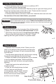
Install guide 8050C Caution Tools To avoid electrical shock and to prevent damage to the furnace, air conditioner, and thermostat, disconnect the power supply before beginning work. This can be done at the circuit breaker, or at the appliance. You will need #1 Phillips screwdriver (small) and Drill with 3/16-in. (4.8mm) bit for this installation. 1 Location .On replacement installations, mount the new thermostat in place of the old one if possible. .
2 Label Wires from Old Unit .Switch electricity to the furnace and air conditioner OFF; then proceed with the following steps. .Remove cover from old thermostat. Most are snap-on types and simply pull off. Some have locking screws on the side or front. These must be loosened. .Note the letters printed near the terminals. .Carefully attach labels (enclosed) to each wire. Label the wires one at a time. You must have all the wires labeled before you proceed.
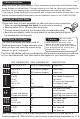
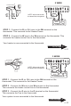
I 5 Gas-Electric Selection REFER to the back of the Control Unit: If you have Electric Heat or a Heat Pump you must place the Gas/Electric jumper in the ELECT position (thermostat controls the Fan). If you have Gas Heat the Gas/Electric Jumper should be in the GAS position (furnace controls the Fan). 6 Heat Pump Switch G Y W RH B . O RC W2 C -F jumper 2 ELECT Gas / Electric jumper Circuit Board 3 4 SHORT C ON F GAS o PUMP o Differential jumper .
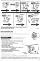
PG 9 Wire Connections 7 Make sure your wires are labeled. This is necessary to determine which step-by-step wiring diagram you should use. This may require you to find the 'other end' connection for each wire on your heating or air conditioning equipment and read the label there. If you have a Zoned Heating/Cooling system with multiple thermostats, please refer to our website at www.ritetemp-thermostats.com for installation notes or call 1-888-515-2585.
NOTE: Wires marked with dotted line are optional.
ace From Furn C 2 WIRE R or RH W Thermostat NOTE: Wires marked with the dotted line are optional. jumper wire C R W HEAT Power HEAT FURNACE STEP 1 - Connect the R (or RH) wire to the RH terminal on the thermostat. This connects to the Heater Power. STEP 2 - Connect the W wire to the W terminal on the thermostat. This connects the heater control line to the thermostat. Your heater is now connected to the thermostat.
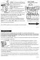
ce From Furna it and AC un Y RH or R G C W 4 WIRE STEP 1 - Connect the Y wire to the Y terminal on the thermostat. This connects to the Cooler compressor. NON-HEAT PUMP Thermostat jumper wire STEP 2 - Connect the RH or R wire to the RH terminal on the thermostat. This connects the Heater/Cooler Power. RH C Heat Power W Y G Heat Cool Comp FAN HVAC SYSTEM STEP 3 - Connect the W wire to the W terminal on the thermostat. This connects to the heater control line.
NORMAL 2 Stage Heat System al From Norm stem two stage sy STEP 1 - Connect the G wire to the G terminal on the thermostat. This connects the Fan. W STEP 2 - Connect the W wire G C to the W terminal. This R connects the 1st stage heat. STEP 3 - Connect the W2 wire to the W2 terminal. This connects the 2nd stage heat. STEP 4 - Connect the R wire to the RH terminal on the Thermostat. This connects to the 24vac power. W2 jumper wire Thermostat W2 R C NOTE: Wires marked with the dotted line are optional.
W or W2 STEP 1 - Connect the G wire to the G terminal on the thermostat. This connects the Fan. Y STEP 2 - Add a jumper wire O between W and Y. or STEP 3 - Connect the Y wire to B C the Y terminal on the thermostat. G This connects the Compressor. R STEP 4 - Connect the O or B wire to the O or B terminal on the thermostat. (If you have both O and B wires, use the O and tape off the B). This connects the change over valve. STEP 5 - Connect the R wire to the RC terminal on the Thermostat.