
Use Manual


1
SETUP
OPERATION
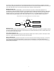
The DTX-145M uses two connectors for operation and one for factory use. The sub D-15 contains signal, control and
power lines and the RF connector receives low level signals and transmits power. The third connector on the unit is
used for initial factory flash programming of the unit. The radio’s eight transmit and receive frequencies are programmed
via a PC. Pins 1, 2 and 3 of the DB-15 connector select the channel. The receiver bandwidth is fixed in either a wide or
narrow bandwidth and should be ordered as such from the factory. The transmitter can be programmed for either wide
or narrowband deviation on a channel by channel basis. A monitor input activates both speaker and auxiliary outputs,
allowing a modem to continually search for a signal. A high/low RF power control pin allows selection of transmitter
power level. Separate microphone and auxiliary inputs allow either pre-emphasized voice or flat data to be transmitted.
Only one input should be driven at a time. Separate speaker and auxiliary outputs allow either de-emphasized voice or
flat data output. A carrier detect output is pulled high when the channel is busy. Alternately, the MON ITOR input can be
used as a carrier and tone detector output. Adjacent to the DB-15 connector, a dual colored LED appears on the sub D-
15 edge of the board. It has the following functions:
Bright RED while transmitting
Bright GREEN when carrier is present on channel
Bright blinking RED when PLL is unlocked, PA overheats or TX regulator voltage not present while attempting to
transmit
Dull blinking red when receiver PLL is unlocked or TX regulator remains on in receive mode.
INSTALLATION
The antenna should be installed in a location to minimize radiation to the DTX-145M board and DB-15 connector
harness. Antenna positioning is also important in minimizing interference to the receiver. PCs and motors are notorious
producers of electrical noise. In a noisy environment the receiver squelch level can be raised to avoid unwanted
spurious reception.
To maximize transmission power, the power supply cable should be of sufficient gauge to minimize voltage drop.
Measuring the voltage between pin 6 and pin 15 on the DB-15 connector while transmitting will show the actual radio
voltage. For higher duty transmitter cycles, heating of the board should be considered. An external heat sink can be
added to the bottom of the board only version using the two mounting holes on both sides of the RF PA shield. On the
shielded board model the shield will help heat sink the unit. On the encased model the heat is conducted out of the
aluminum end cap opposite the connectors. When transmitting with higher duty cycle usage at elevated ambient
temperatures, without heat sinking, the internal board heat may push the reference oscillator Y301 temperature higher
than the 60 ºC specified limit for 2.5 ppm (VHF). Some form of additional cooling may be employed to avoid this
situation. Operating at voltages higher than 14 volts with high duty cycle usage can generate additional heat from the
regulator. The transmitter voltage regulator regulates the voltage to around 13.5 volts. The regulator will dissipate power
while transmitting when the supply voltage exceeds 13.5 volts. A thermistor, or temperature sensitive resistor,
monitoring the voltage regulator temperature will trigger a transmitter shutdown with excessive heat. Also, a thermistor
monitoring the final RF FET will trigger a transmitter shutdown if it overheats.