
Use Manual


2
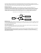
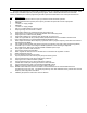
SUB D-15 PIN CONNECTOR
The DTX-145M is equiped with a 15 pin female sub D connector with the following functions:
Pin# Function
1 Least significant channel select bit (CS0)
2 Channel select 1 (CS1)
3 Most significant channel select (CS2)
4 Microphone input
5 High/ low power select (pull low to get low power)
6 + 9 to 17 VDC input
7 Auxilary input
8 Auxilary ouput
9 PC programing port
10 Volume control (RSSI option)
11 Auxilary monitor input (pull to ground to open squelch). Can be used for tone detect, see below.
12 Speaker output
13 Carrier detect output (pulls to 3.3 VDC through internal 390 ohms)
14 PTT (pull to ground to transmit)
15 Ground
Channel Select (pins 2,1,0)
Three lines control the channel selection; CS2, CS1, CS0. The inputs have binary weighting of 4, 2 and 1 respectively.
They are internally pulled up in the microcontroller. Tying an input to ground gives it a zero weighting. Thus, if no inputs
are tied low, channel eight is selected (7 binary).
Microphone (pin 4)
An electret microphone can be connected to the microphone input at pin 4. An internal 33 k ohm resistor tied to +3.3
VDC on the DTX-145M supplies power to the microphone. An internal 1k ohm resistor connected to pin 14 allows PTT
when the microphone PTT is pressed. The microphone sensitivity can be adjusted with the AUX_IN gain pot.
High/ Low Power Input (pin 5)
Pulling this input to ground will yield the low power setting of about 2 watts of transmit power (factory preset level).
Unconnected it will also transmit 2 watts. Actual power output will depend on supply voltage and programmed setting.
Power Input (pin 6)
A power source of 9 to 17 VDC with 2 Amp capability should be connected here. Once power is applied to pin 6 of the
radio, the microcontroller will start and load the receive frequency of the channel designated by CS2, CS1 and CS0
(pins 3, 2 and 1).
Auxiliary Input (pin 7)
This input has a frequency response from 8 Hz to 2500 Hz. The input gain is set up at the factory to produce +/- 3 kHz
deviation (1.5 kHz for narrowband channel) when a 300 mV peak-peak signal is applied. The gain can be adjusted by
the programmer for other input levels. Gain is PC adjusted by a 256 position 100k ohm e-pot. Higher voltage level
inputs need lower gain and therefore have coarser tuning per pot position. Recommended range is 100 to 1000 mV
peak-to-peak. R356 on the PCB can be removed to obtain 10% of the audio gain and allow higher level signals.
Auxiliary Output (pin 8)
An output loading of 600 ohms or greater should be applied to this output. With a 600 ohm load the output exhibits a
frequency response of 12 Hz to 2500 Hz. Higher load impedances will lower the low end frequency response. The
output is adjustable via the programmer. It is preset at the factory to give 1 volt peak to peak output when receiving a +/-
3 kHz (1.5 kHz for narrowband channel) deviated signal. Output range is 0 to 3 V peak-to-peak. It is suggested keeping
it below 2 V pp since the IF output is DC coupled and a frequency error of 1 kHz will cause a 0.2 V shift on narrowband.
Programming Port (pin 9)
This line is a bi-directional programming port to be connected to a RITRON programming cable. The other end of the
programming cable connects to the PC’s serial port 25 pin D-sub connector. The appropriate DTX-145M programming
software must be run for configuring the transceiver (See programming the radio on page 10).
External Volume Potentiometer (pin 10)